
Programming tool for CAN displays
![]()
![]() Last modified: 2026-05-07 (YYYY-MM-DD)
Last modified: 2026-05-07 (YYYY-MM-DD)
Available online at www.mkt-sys.de/MKT-CD/upt/help/progt_01.htm.
Contents
-
Programming tool for CAN displays
- Introduction
- Installation
- The Main Window
-
LCD simulator window and LCD device selection
- Device Selection / LCD Settings (screen resolution, colour model, landscape/portrait mode)
- Communication Channels
-
Application Variables
- Properties of display variables
- Finding all references to a variable, function, signal, string, etc (globally)
- Variables on SDO channels
- Variables on PDO channels
- Variables connected to the own CANopen object dictionary
- Variables connected to CAN-Signals
- Variables connected to 'openABK'
- Data Breakpoints (to stop on assigning certain values to a certain variable)
-
Settings (on tabsheets and dialogs in the programming tool)
- Parameters in the right part of the 'Settings' tab
- Parameters in the left part of the 'Settings' tab
- CAN bus timing parameters (dialog)
- General Terminal Options (dialog)
- Optional Setup (formerly only configurable in the device's own setup menu)
- Checking the supported graphic functions
- Creating a UPT File Description (string displayed in the 'App-Selector')
- Simulation of the memory card (on a PC, as replacement for the memory card in a 'real' device)
- Checking external file references (in the application)
- Creating a UPT File Description (string displayed in the 'App-Selector')
- Parameters in the right part of the 'Settings' tab
- Definition of a Text Array (antiquated, for devices without script language)
- Display Page Definitions
- Introduction to programmable display pages, with an
overview of available display elements - The page definition header
- Definition of display lines (manually, without the graphic editor)
- Properties of a display line (position, font, colour, text, ... )
- The Format String with backslash sequences and HTML-like 'tags'
- Edit Fields on a programmed display page
- Buttons (and similar 'active graphic areas')
- Icons (bitmap graphics)
- Using Display Lines as Menu Items
- Bargraph diagrams (optional)
- Y(t)- and X/Y-diagrams (optional)
- Multi-Line Text Panels (for the script language)
- Graphic Panels (displaying script-generated 'Canvas' graphics)
- Inserting other grahic elements on a display page
- Overlapping graphics
- Touchscreen support (in certain terminals)
- Multi-Language Applications (and how to realize them)
- Introduction to programmable display pages, with an
-
The "simple" editor for display pages
- The page editor's toolbar
- Dialog box for alphanumeric display elements
- Creating and modifying polygons
- Creating an anlog meter (needle instrument)
- Defining Events - overview
- Defining Events - the definition window
- Defining Events - the definition language
- Global and Local Events
- Global Event Catalog
- An alternative for 'events' : the Script Language (only for 32-bit CPUs)
- Assistants
- Display Page Overview ("all pages")
-
The Icon import screen
- Reserving memory for icons (and other special features)
- Flexible memory usage (for newer terminals with 32-bit CPU)
- Determining the Flash memory usage in the target
- User defined fonts
- Debugging
- CANopen Configuration
- CANopen SYNC configuration
- CANopen NMT configuration
- Devices with 'CANopen V4' (most terminals with 32-bit CPU)
- The CANopen object dictionary (OD)
- PDO-Mapping with the Terminal Programming Tool(for CANopen V4 only)
- EDS files (electronic device specification)
- EDS/DCF-Generator to transfer the CANopen-configuration into a PLC software (like CoDeSys)
- Data Transfer between programming tool and device
- The UPT's internal System Menu
- Display-, Audio-, CAN-Bus-, and other items in the System Setup
- Network Setup (for TCP/IP, UDP, etc)
- Power-on/off behaviour of the device, e.g. Wake-up via CAN
- Unlocking 'special' features
- Remote Control (for the system menu)
- Storage Directory
- The Error Page
- Mousecklicks into the 'Errors & Messages' list
- Error classes an display of other messages (CAN, CANopen, ..)
- Display of the Trace History under 'Errors & Messages'
- Introduction
-
The Display Command Interpreter
- Numeric Expressions
- Interpreter Functions
- List of interpreter functions by alphabet
- Keyboard Functions
- Arithmetic and other functions
- Konvertierungsfunktionen 'val' (value) und 'eval' (evaluate)
- CANopen-specific functions
- Generic CAN functions: CAN bus status flag, CAN reception, CAN transmission
- String Functions
- String Expressions
- Real Time Clock functions
- Timer functions
- Bit-Counting function ("nbit")
- Functions to access non-volatile values (nv[0..31])
- Functions to read (onboard-) analog and digital inputs
- Functions for the rotary encoder knob (rot.xxx)
- Functions for an (optional) analog joystick
- Interpreter Commands
- The script editor / compiler / debugger
- Appendix
- Frequently asked questions (separate document)
- Manuals for the programmable terminals (in PDF format)
- Boot Screen (optional graphics displayed after power-on)
- CANopen objects inside the UPT
- SDO error codes
- FAQs ("frequently asked questions")
- Troubleshooting (and older FAQs)
- Glossary
- Author's Info
- Revision history of the UPT family
Programming tool for CAN displays
Introduction
This document is part of the online help system for MKT's Terminal Programming tools for UPT (User Programmable Terminals with CANopen) and devices without CANopen (like MKT-View II/III/IV - see feature matrix).The original purpose and design goals of the programmable devices was...
- show signals received via CAN bus in numeric form on the built-in display
- switch between different programmable display pages (like 'motor', 'gearbox', 'brakes'), controlled by the operator
- send special ("programmable") CAN messages in response to user input
- fast boot, only a few seconds between power-on and execution of the user's application
- low cost (the original device used an 8-bit controller and just a 128 * 64 pixel LC display)
- graphic display- and control elements like bitmaps, buttons, bargraphs, diagrams, tables
- a device simulator, integrated in the programming tool, to develop applications without 'real' hardware
- a script language to control those elements, and to 'talk' to external devices and control units
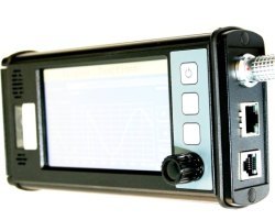
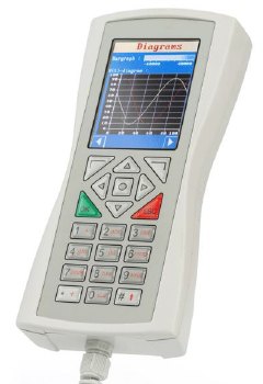
- support for larger displays (in 2015, up to 800 * 480 pixel TFT displays with 64k colours)
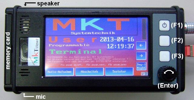
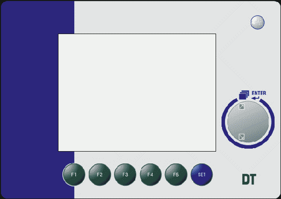
Example for a recent user-programmable display (2013) : MKT-View III with 2*CAN and Ethernet on the right side.
A list of devices supported by MKT's programming tool can be found in the feature matrix.
Beginners may want to start with the presentation of the programming tool, which is heavily linked to this help system (only in German language so far). Users 'in a hurry' will find explained examples for various applications either directly in the 'programs' folder of the programming tool, or (for the non-CANopen variants, where CAN signal definitions are imported from a database) create their own appications from scratch as explained here (beginning with the import of CAN signal definitions). Last not least, for advanced users, the documentation of the script language contains a huge list of script examples (including topics like CAN reception and transmission, digital signal processing, file access, internet access, event handling, multi-language applications using string tables, etc).
Some of the new functions explained in this manual are available since
2024-12-06
( = compilation date in ISO-Format, applies to the device firmware and the programming tool) .
Keyword Index ("from A to Z")
The keyword index (in alphabetical order) has been moved into a separate file to speed up loading the index from other documents.Context- and Command-specific Help System
The entire help system consists of a collection of HTML documents, which can be viewed with any modern browser. The antiquated Microsoft-Help-System has been withdrawn, last not least for security reasons (and because it was always a pain to work with, requiring a 'help compiler', etc).If you use a good browser like Firefox, and open the help system from the utility, this document will automtically be scrolled to the right position. The same was possible with IE6. But with IE7 and IE8, this doesn't work anymore. Now it's your decision which browser to use.
The HTML-browser used by the programming tool to show the help pages is freely adjustable (regardless of the "Default Browser" on your system). To define the browser for showing the help pages, select "Help" in the programming tool's main menu, then "Define HTML Browser Command Line".
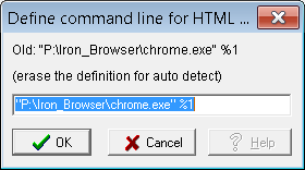
(Example using an alternative browser, on the author's PC installed under "P:\Iron_Browser")
Note: A few 'newer' devices with at least 4.3" display may have a built-in help system, invokable from the devices's System menu and certain submenus.
Some 'printable' manuals are located in "DOKU\MANUAL.DOC": "DOKU" ( a bit outdated), furthermore a description of the System Menu, and finally the special functions for terminals with CANdb (instead of CANopen). Note: The latter document is available in german language only.
Further infos (sample programs, translations into other languages, possibly some device descriptions) can be found in the index or on the MKT website.
Context-specific help:
- Press F1 if you need help on any component of the programming tool's user interface, for example if you want to know what the "display property"-window is for. Before pressing F1, click on the element (to set the "focus" to the dialog element).
-
Press F2 if you need help on one of the
interpreter commands of the User
Programmable Terminal.
For "simple" edit-fields, place the blinking cursor on the command you need help about, then press F2.
For "tables", click into the cell with a command, leave the mouse on the command, then press F2.
The programming tool will then try to analyze the contents of the input field where the cursor is blinking, and switch to the help page with information on that particular command.
Note on both types of "specific help":
- These help functions only work, if the main window of the programming tool is the "active" window. You can tell the active window from all other windows by the color of the window title, a blue window title usually indicates the active window.
For translators of the help system into other languages: please contact the
author for details on the HTML anchor names !
New devices with at least 4.3"-display and sufficiently large Flash memory
(e.g. MKT-View III/IV/V) have a internal help system ("browser")
which can be opened from the device's System Menu.
The internal help system only covers topics like the system menu itself,
the CAN snooper, and other integrated diagnostic tools, but it doesn't cover
the aspect of developing applications for the MKT-View.
The 'built-in' help pages (in the UPT device firmware) can be extended
or replaced by applications-specific pages. An example 'index'-page can
be found in the subdirectory 'fonts'(!) after installing the programming
tool, file index.htm.
How to open the internal help system via script is described
here (system.show_help),
and the specification of the file format is here.
Disclaimer, Legal Issues
Namings for products in this manual, that are registered trademarks, are not separately marked. The same applies to copyrighted material. Therefore the missing ®(r) or ©(c) does not implicate, that the naming is a free trade name. Furthermore the used names do not indicate patent rights or anything similar.CANdb® is registered trademark of Vector Informatik GmbH.
NTCAN API is copyright (c) by ESD electronic system design GmbH.
PCAN Dongle and the PCAN API is copyright (c) by PEAK-Service GmbH.
Microsoft, Windows, Win95, WinNT, WinXP® are registered trademarks of Microsoft Corporation.
The Hershey fonts are a collection of vector fonts developed circa 1967 (!)
by Dr. Allen Vincent Hershey while working at the U.S. National Bureau of Standards.
The software and accompanying written materials (including instructions for use) are provided "as is" without warranty of any kind. Further, MKT Systemtechnik does not warrant, guarantee, or make any representations regarding the use, or the results of the use, of the software or written materials in terms of correctness, accuracy, reliability, currentness, or otherwise.
The entire risk as to the results and performance of the software is assumed by Licensee and not by MKT Systemtechnik or its distributors, agents or employees.
THERE ARE NO OTHER WARRANTIES, EITHER EXPRESS
OR IMPLIED, INCLUDING BUT NOT LIMITED TO
IMPLIED WARRANTIES OF MERCHANTABILITY AND FITNESS
FOR A PARTICULAR PURPOSE,
WITH RESPECT TO THE SOFTWARE, THE ACCOMPANYING
WRITTEN MATERIALS, AND ANY ACCOMPANYING HARDWARE.
MKT Systemtechnik
Haßkamptraße 75-77
32257 Bünde (Germany)
Phone: 05223/493933-0
Fax: 05223/493933-20
This software and appendant hardware may influence or control a CAN-based system or network. Your actions can therefore lead to severe damages. For this reason, only persons which have understood the possible consequences of their actions with this product may use it.
The manufacturer's warranty shall be restricted to the terminal hardware itself, but does not cover effects caused by its use in a CAN network. Neither MKT Systemtechnik nor its employees or partners will be liable for improper use of these products.
HIGH RISK ACTIVITIES
The Software is not fault-tolerant and is not designed, manufactured or intended for use or resale as on-line control equipment in hazardous environments requiring fail- safe performance, such as in the operation of nuclear facilities, aircraft navigation or communication systems, air traffic control, direct life support machines, or weapons systems, in which the failure of the Software could lead directly to death, personal injury, or severe physical or environmental damage ("High Risk Activities").
MKT Systemtechnik specifically disclaim any express or implied warranty of fitness for High Risk Activities.
If you do not agree to the above limitations, please uninstall the software, and send the hardware back to the distributor IMMEDIATELY. He will then refund the price you paid for the unit. Customers of MKT Systemtechnik please contact via email, info (at) mkt (minus) sys (dot) de.
Installation of the programming tool
Download the programming tool that supports your hardware from the MKT-Webseite. For devices parametrized via 'Database for CAN' (*.dbc, as used in passenger cars), use 'InstallCANTerminalProgTool.exe'. If the web browser or file manager doesn't automatically unzip the file downloaded from InstallCANTerminalProgTool.zip, unzip the executable file manually.For devices with CANopen 'V4' (as used in the automation industry and certain trucks), use 'InstallUptTool2.exe'. For ancient devices (like "UPT515") with CANopen V3, use the installer named 'InstallUptTool1.exe'.
If you also wonder why there are these three different programming tools, follow this link .
If the HTML-based help system doesn't work properly, you may modify the
command line to invoke the browser (e.g. Firefox, Chrome / Iron, or if nothing else is available "Internet Explorer"),
as described here. That way, you can use any
browser as 'help system' for the programming tool, not necessarily the system's "default browser".
Notes on Windows 7 / 8 / 10 / 11
Thanks to a modified method to access the program's own configuration file (since December 2019, stored in the application's own folder), installation and operation worked flawlessly without admin privileges - at least when tested on a 64-bit Windows 10 system in December 2019.
Since then, the notes further below are only necessary if you decide to install the programming tool in the windows 'Programs' folder (or whatever the default folder for installed 32-bit application may be on your machine).
Unfortunately we never saw the installation on a PC with 'english' windows locale, so below is the german original, describing how to update the ‚CANdb-Terminal Programming Tool'
- Programm starten (rechte Maustaste > Als Administrator ausführen)
- Menüpunkt Hilfe / Auf Updates prüfen (per Browser)
-
Das MKT-Browserfenster öffnet. Wählen Sie den Link >here<,
der
Download wird automatisch gestartet. -
Schließen Sie das ‚CANdb-Terminal Programming Tool‘ nachdem
der
Download beendet ist. -
Wichtig: Installieren Sie dieses Update aus dem Download-Ordner Ihrer
lokalen Festplatte (rechte Maustaste > Als Administrator ausführen)! -
Folgen Sie den Anweisungen. Danach starten Sie das ‚CANdb-Terminal
Programming Tool‘ neu,
Sie arbeiten nun mit der aktuellsten Version.
Another annoyance related with Windows 7/8/10/11(?) are the desktop icons, created by the installer.
By default, they will also try to launch the program without admin rights.
Consequence: The program may be unable to write its own configuration file (*.INI), located in its own directory.
Workaround: Modify the desktop shortcut ("icon on the desktop") to launch the programming tool as administrator.
Here is how to achive this with a certain flavour of windows (as usual, things may be different in other and future versions of windows..) :
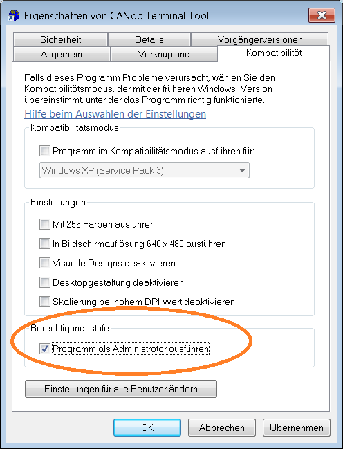
- After installing the program, right-click the shortcut ("icon on the desktop")
- In the context menu, select 'Properties' ( ? - 'Eigenschaften' on a German PC )
- In the dialog window which appears then, select 'Compatibility' (tab or menu or whatever..)
- Set the checkmark for option 'Run this program as administrator' ( ? - 'Programm als Administrator ausführen' on a German PC)
- Click OK to close the dialog window
Reason for the necessity of an administrator accound under Windows 7 / 8 / 10 :
In opposition to earlier windows versions, these days Windows doesn't grant
write permission for files which have been placed in the application's own
directory (see examples below). But, for tradional reasons,
the installation script keeps 'all files in one place' instead of spilling
all over different folders of your harddisk (like, in german, those annoying
"Eigene Dateien", "Dokumente und Einstellungen", and similar crap which changes
with each new version of Windows). For that reason, you will still find the examples in the following folder :
- PC with 'german windows' :
- C:\Programme\MKT\CANdbTerminalProgTool\Programs\*.cvt; *.upt
- PC with 'english windows' :
- C:\Program Files\MKT\CANdbTerminalProgTool\Programs\*.cvt; *.upt
oder (possibly, depending on where Microsoft wants to have 32-bit applications
installed) :
- PC with 'german windows' :
- C:\Programme (x86)\MKT\CANdbTerminalProgTool\Programs\*.cvt; *.upt
etc...
If you prefer to follow the "new rules" (by Microsoft) and store 'your files' where they want you to, you can change the default directories after installation of the programming tool, on the tool's 'settings' tab.
Alternative to circumvent the trouble with Windows "Vista"/7/8/10/11 and non-writeable folders and stupidly padlocked files (![]() ):
):
Do not install the program where Microsoft wants you to install everything.
Instead, install the software in a directory of your choice (where you will have unlimited write permission),
outside the Microsoft-dictated 'Programs' folder. For example (again, on a German PC):
- Instead of installing the software somewhere under
- "C:\Programme\MKT\xyz", alias "C:\Program Files\MKT\xyz", or wherever they want you to,
- install the software under
- "C:\MKT\xyz" .
- C:\Documents and Settings\All Users\Documents\no idea where.. (Windows XP, english)
- C:\Dokumente und Einstellungen\Alle Benutzer\Faselblah\keine Ahnung wo.. (Windows XP, deutsch)
- C:\Users\Public\Public Documents\...?...\no idea where.. ("Vista", english)
- C:\Users\Frustrated Windows User\Documents\Where the heck are MY FILES\..??.. (some other PC)
If you used the suggested destination (for the programming tool), you will find the samples for your target device at:
| c:\MKT\CANdbTerminalProgTool\programs | (with subdirectories for different targets) |
| c:\MKT\CANdbTerminalProgTool\programs\script_demos | (Examples for devices with script support) |
| c:\MKT\CANdbTerminalProgTool\programs\MKTview2 | (Examples for MKT-View II / III, most without script) |
| c:\MKT\CANdbTerminalProgTool\programs\MKTview4 | (Examples for MKT-View IV, most using scripts) |
Notes about running the programming tool on Linux / WINE
Since November 2025, the programming tool is aware of running on Linux / WINE instead of running on a native Windows host.Some features however could not be put to work on Linux / WINE though, for example accessing a CAN bus interface. As an alternative, the programming tool can communicate with the programmable device via 'serial port', including (in the MKT-View V) the built-in "Virtual Serial Port" (Linux slang) aka "Virtual COM Port" (Windows slang), which in fact uses "USB CDC" ("Communication Device Class"). This works on Linux as well as on Windows.
To allow an application access to the serial port (or USB virtual serial port), and how to assign such a port to a "COM-port" in WINE, please consult the excellent and up-to-date WINE documentation (linked above).
When installed on Linux/WINE, the programming tool automatically adjusts some default settings (e.g. the font for the script editor/debugger will be set to "DejaVu Sans Mono" instead of "Courier New", because the latter rarely exists on a Linux system).
After the installation: Check if a firmware update is available or necessary
After installing a new programming tool, there will usually be new functions available. To make sure that these new functions are also available (functional) in the programmable device, the device's firmware may have to be updated, too. Otherwise, the new functions will only be available in the simulator (which is part of the programming tool) but those functions won't work on devices with outdated firmware..- Hint:
- When invoking 'Check for Update (via browser)' in the tool's 'Help' menu,
you will see an excerpt from the version history, with the latest changes
on the beginning of the list. Some of these modifications don't just apply
to the programming tool, but to the device firmware.
So you can decide for yourself if you need those 'new features' or not.
If your web browser cannot be invoked via the tool's Help menu, you can reach the same website from here through the following link:
www.mkt-sys.de/check4update/ctptwin1.htm
-
Example:
-
 MKT-View III  with CANdb + Logger

 ISO-Date: 2013-07-22 16:24:00
 Software: art11392 V0.2.4-1
      (...)
 Compiled: Jul 24 2013 (RV)
      (...)
   press ENTER to quit
- Explanation:
-
'ISO-Date' is the current date and time in ISO-format. It doesn't have anything to do with the firmware compilation date !
'Software' is the identification of the device firmware, including the software article number (art...) and the version number (Vx.y.z-b) .
'Compiled' is the the firmware compilation date. Details about this in the next sub-chapter.
Details about how to update the firmware can be found in the programming tool's 'firmware' folder (after installing the tool, of course). The 'firmware' folder contains the most recent firmware files for the most common devices by MKT, and a description of how to update the firmware (fwupdate.htm) .
For rarely sold, or custom developments, the firmware is not included in the programming tool.
If the programming tool was installed into the recommended directory, you will find the firmware in the following folders:
| c:\MKT\CANdbTerminalProgTool\firmware | (for devices with 'DBC', e.g. MKT-View II / III / IV) |
| c:\MKT\UPT_ProgTool2\firmware | (for devices with CANopen, e.g. UPT128, UPT800 ) |
In some cases, there is a 'DBC' (CANdb)- as well as a CANopen-firmware aviablable for the same hardware - see Feature-Matrix.
(Links to the Feature-Matrix - click on image to check if there's a "CANdb" or "CANopen" firmware available for your device)
Details about the Firmware Compilation Date
This entry in the table of 'Terminal Constants' is the compilation date, in ISO8601 format (YYYYMMDD) of the firmware used in the programmable device. The programming tool needs to know this parameter to decide if a certain function is available in the target system (or, if some functions use a different syntax, etc). Also, if the programming tool "knows" the firmware compilation date of your target device, it will not offer certain function in selection lists ("combo boxes") to avoid problems later, when you transfer the display application via memory card.- Example:
- On November 27, 2009, the syntax of certain graphic display elements has been modified in both the programming tools, and in the firmware of a few devices produced by MKT. Since then, the width and height of a display element is entered in two extra columns of a page's display definition table. Older devices (for example the old "MKT-View") don't support this, and thus loading a "new" application into such an "old" device would cause problems.
To avoid such problems, the programming tool will only show the columns "W" and "H", if the firmware compilation date is at least 20091127 (ISO8601, YYYYMMDD).
Originally, the programming tool was always connected 'directly' (via CAN or RS-232) to the programmable device, and could read the compilation date of the device when downloading or uploading the application.
With the more-common method of "transferring" the application "as a file on the memory card", this is not possible anymore, because no data can be transferred from the programmable device back to the PC / programming tool !
Due to this 'unidirectional' transfer (from PC via memory card into the device), the programming tool can only be informed 'manually' if about the firmware revision / compilation date of the to-be-programmed device. The device's firmware compilation date can be read out through the system menu . Details, and how to invoke the system menu, are in document #85115.
- Example: "Old" MKT-View (MKT-View "Plus"), Firmware #11089 .
-
Compilation date 2008-12-02 (shown as "Compiled: Dec 2 2008" in the
ugly __DATE__-format of the C-Compiler)
The value displayed in the programming tool under "Settings"..."Terminal constants"..."Firmware compilation date" must never exceed 20081202 then.
Otherwise, there may be the risk that you use a feature in the programming tool which doesn't exist in the firmware yet !
If necessary, the date can be modified via mouse click on the compilation date (numeric value in ISO-8601 format)
You can check if there is a newer firmware (along with a newer programming tool) through the menu "Help" .. "Check for Update", or (if a stupid or paranoid web browser doesn't co-operate) in the file readme.txt in the "firmware" folder after installing a new programming tool .
Known problems with older firmware are listed in the firmware Release Notes .
See also: firmware update, software revision history (web link) .
Program start with or without 'disclaimer'
After installation, the programming tool initially starts starts with the display of a 'Disclaimer'.The disclaimer is a dialog window in which the user's language and his self-assessed expertise level ("user profile", Novice / Intermediate / Expert) can be selected.
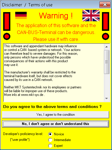
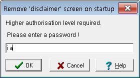
"Disclaimer" dialog, displayed on program start
As already mentioned in section 'Legal Issues / Terms of Use', the disclaimer display (at program start) can be removed by entering a certain password.
You will know that password after reading this documentation - especially the chapter about firmware updates.
Removal of the programming tool's 'Disclaimer'
If you do agree to the disclaimer, and have understood the possible consequences from the use of this software, here's how to remove this disclaimer window on every program start:
In the main menu, select "Tools"..."Remove disclaimer on startup".
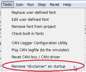
The same password dialog may also pop up in other situations which require a higher
level of authorisation, for example when updating device firmware.
The Main Window
The main form represents the window that you see after starting the program.Depending on the user's proficiency level ("Novice"/"Intermediate"/"Expert"), some parts of the user interface may actually be hidden.
- define Communication Channels
- configure the supported communication protocols like CANopen or CANdb (depends on the tool used)
- define Variables that use Communication Channels
- define Display Pages that you want to have on the User Programmable Terminal
- define Icons for your terminal application
- show an overview of all your "programmed" display screens
- display and modify some settings of the device and the programming tool
- show errors in an error history window
Back to the table of contents
The programming tool's main menu
The programming tool's main menu contains the usual functions to load and save files, editing functions, some more specific functions to transfer the application into the terminal, and functions to change settings and options of the programming tool.- File
- Functions to load application from a file (*.upt or *.cvt), save as file, define password for the application, etc.
- Assistant
- may help you to create simple applications, or invoke dialog screens to link menus in the terminal, and replace variables (which are shown on the current display page)
- Edit
- Contains a global search function, and functions to create and modify display pages. Many other "editing" functions can be invoked through popup menus when clicking on the control elements with the right mouse button !
- Transfer
- transfer the application into the terminal, firmware update, selection of the (serial) interface
- View
-
Switch to other windows of the programming tool, for example:
LCD simulator, Watch window, Test Command Window, File References. - Options
-
Modify options of the programming tool, query supported graphic functions,
change memory distribution in the terminal. The following options
affect the appearance of the programming tool's user interface (GUI)
but not the application created with the tool:
- User profile "Novice" :
- Novices may configure simple numeric displays by picking signals from a list,
and mainly (almost exclusively) use the 'simple' graphic editor.
The programming tool only displays the basic tabsheets which are 'always' required to create a very simple display application.
- User profile "Intermediate" :
- The more experienced user doesn't freak out when seeing a lot of tabsheets in the upper part
of the programming tool (he knows which one to chose). The programming tool still starts with the
graphic editor instead of the tabular display (with 'all display elements on the current page').
- User profile "Expert" :
- An expert user prefers to enter sourcecode directly (for the display definition and the script),
and is familiar with tables, pixel coordinates in numeric form, the versatile format strings.
In this mode, the programming tool starts with the tabular display of all elements on the first display page. The Expert knows how (and when) to switch between graphic and tabular display. He sees all tabsheets in the programming tool.
- Invoke internal tools or external auxiliary programs, which may be installed additionally - for example the font editor, CAN logger utility, CAN Bus Simulator, etc.
- Icon
-
Import graphics from bitmap files
- Run, Stop, Reset
-
start, stop, and reset the simulated application on the PC (firmware simulator integrated in the programming tool).
Note: An application can only be edited while the simulation is stopped.
'Reset' (in the programming tool's main menu) simulates a power-on reset (aka 'cold start' of the target. 'Run' resumes the program (and script-) execution at the point where it was stopped (manually) or paused (by hitting a breakpoint).
- Help
- Show help on various topics. Requires a properly installed HTML browser, but not necessarily an internet access
Back to the description of the main window
Status Bar
At the bottom of the main window is a status bar, which displays some information about the current system state (e.g. "Transfer in progress" and so on).
![]()
The second panel from the left (here: "Running") shows a quick info about the current state of the programming tool or the application program. Some possible labels are:
- Running: Your application is running (i.e. it is being executed)
- Stopped: Your application has been stopped for any reason (e.g. hitting a code- or data- breakpoint)
- Transfer: A program upload or download is in progress.
The right field in the status bar will display the last error message (if
any) or other system messages. In the example shown above the last system
message was an indication that the CAN interface has been successfully
initialized.
You may switch to the error page by double-clicking
into the status message field.
The rightmost field in the status bar may also show info about the
'word' (or sub-expression) currently under the mouse pointer.
For example, the current value of a variable, expression, or sub-expression
can be inspected by hovering over certain grid cells with the mouse
as explained here.
The display of the last error message has priority over 'mouse pointer info'
in the status line. To clear a (static) error message in this field and
switch back to 'inspect-anything-via-mouse' - mode, click into the message.
For debugging purposes you may also send a command string to the UPT's
command interpreter by typing it into the
rightmost statusfield.
return to the description of the main window
LCD simulator window and device-dependent selections
The LCD simulator window is used to show the contents of the LCD screen, which you would see after loading your application into the user programmable terminal.
This window shows the current display page.
As long as the LCD simulator window has the "input focus" (blue title background), all keyboard inputs will be passed on to the terminal simulator.
This allows you to test your programmed event handlers etc.
The LCD simulator window can be moved and sized independent of the main window. You may even maximize it to a real "full screen view". The panel below the simulated display shows the state of (optional) LED's, digital in- and outputs. If you don't need this, or run out of (PC-)screen space, turn the lower panel off through the simulator's menu.
By clicking into the LCD simulator window with the left mouse button, you can select (or move) a single text display line. The MAIN window of the programming tool will automatically switch to the display definition tab ("Page N") where you can modify all properties of the selected line.
Holding the left mouse button pressed on a visible display line in the simulated display while slowly moving the mouse allows to move the display line aroud (only works for normal text display lines, not for general graphic commands like "line", "rectangle" etc).
When simulating terminals with a touchscreen, the left mouse button is the replacement for the "finger" (or touch pen). To check if the simulated device has a touch screen or not, use the dialog for supported graphic functions.
Clicking into the simulator window with the right mouse button opens a popup menu, which allows you to insert several display elements on the current page, and to enable the mouse wheel as a replacement for the terminal's rotary encoder knob (while the simulator is running). The option 'stay on top' (ex: 'always in the foreground') may be helpful if you only have one monitor connected to your PC, and want to debug the application (or the script) with the tool's main window maximized.
If there are many overlapping graphic elements
on a display page, it may be difficult to select a certain element via mouse-click
in the LCD simulator window. In such cases, as an alternative, you can use the
mousewheel to switch to a certain display element, while the input focus is
on the definition table
(in the main window). This is possible because the 'synchronisation' of the
currently selected object in the LCD simulator and the display definition table
works in both directions (from simulator to definition table, and from definition
table to simulator).
To have all display elements temporarily marked in the simulator,
press and hold the Control key (aka 'Strg' on a german keyboard).
This feature was initially used for software development, but it also helped
a lot when trying to understand a customer's display application, which used
a lot of overlapping graphics.
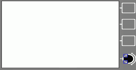
With that option enabled, graphic areas will be marked by transparent
markers with different colours (to distinguish them when overlapped),
with the number (zero-based index) of the display element in the upper left corners:
![]()
Display in the LCD simulator with multiple transparently marked elements.
The simulator can be configured to mark objects 'never', 'always' or via CONTROL key.
Independently of the transparent colour markings shown above,
when clicking into the LCD simulator (unless 'running' a simulation),
the programming tool tries to find the definition of the graphic object,
and -if successful- switch to the object's definition, to highlight
the definition on tabsheet 'Display Lines'
or 'Other Commands' (depends on where
the object was found). In any case, since a single definition line may
contain multiple graphic objects (or areas), the part of the string that
rendered the object will be highlighted by a
green background in the table.
You can copy the contents of the simulated LCD into the windows clipboard through the simulator's menu (button), "Copy image to clipboard". This simplifies making screenshots of the simulated LCD screen for the documentation (e.g. user's manuals, etc). You can also transfer screenshots from a real terminal into bitmap files as decribed in the document about Remote Control via CAN.
If the LCD settings of the simulator don't match the display in your target device, you have to enter the LCD simulator settings to adjust them.
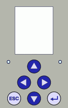
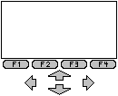
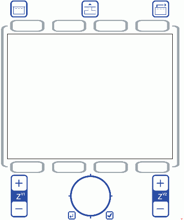
- Hint regarding the LCD simulator's "frame" or background image:
-
To align graphic buttons or other objects close to the function keys of the
terminal's keyboard, turn on a suitable background picture for the
LCD simulator (in the simulator's menu). In the
backgrounds folder, you will usually find the right
picture (bitmap) for your keyboard. If not (for example because you use a
customer specific keyboard) :
For customer-specific keyboards, usually only the surface will have a different "look", but the position of the keys will usually not be modified. So one of the standard images should be ok. If not, you can make your own background picture with a paint program as a bitmap file. Please note, the black framed region of the LCD must exactly match the size of the simulated display in pixels. Everything inside the LCD must remain white !
For a self-defined background image (like lcdsim_XYZ.bmp) you must also create a matching description file (lcdsim_XYZ.txt) with the graphic coordinates of the keys (which can be clicked to simulate pressing a key). A good example for such a 'background image description' is the file for the MKT-View II .
At the time of this writing (2013-11-14), the installer for the programming tool contained a few 'standard' background images, and a few customer specific designs:
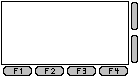 lcdsim_128_64.bmp, used for the old UPT 515 (128*64 Pixel) . |
 lcdsim_128_160.bmp, used for HBG 18 (128*160 Pixel) . |
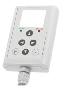
 lcdsim_abe167.bmp, used for 'ABE' handheld (128*64 Pixel) . |
 lcdsim_320_240.bmp, used for old MKT-View (320*240 Pixel) . |
 lcdsim_scandi320.bmp, an OEM design (320*240) . |
 lcdsim_mktview_2.bmp, used for MKT-View II, III (480*272 Pixel) . |
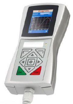
 lcdsim_dt85.bmp, used for DT85 (320*240 Pixel) . |
Your design here ? | lcdsim_no_background.bmp : Select this file if no background image shall be displayed in the LCD simulator. |
return to the table of contents
Device Selection / LCD Settings
Since the introduction of large displays, the programming tool supports different types of displays. Usually the programmig tool will detect the type of the display automatically when uploading or downloading a UPT file from (or into) the target. All required information about the display is stored in the UPT program file. So, if you load a UPT file from disk, the proper LCD settings are automatically adjusted.
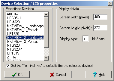
If you have no possibility to connect the programming tool to a target, you must define the LCD type of the simulated device yourself (otherwise the simulated screen will look very different from what you will see later..). To do this, enter the following dialog (from the Main menu, "Options" ... "LCD settings"):
Some example settings:
- UPT515:
-
Screen width=128, Screen height = 64, Display type = 1 (monochrome)
- UPT 167 "monochrome", IPE-View, MKT-View:
-
Screen width=320, Screen height=240, Display type = 1 (monochrome)
- UPT 167 "Color":
- Screen width=320, Screen height=240, Display type = 4 (4 bits per pixel). Discontinued, replaced by "UPT 320 Color" .
- MKT-View, MKT-View "+":
-
Screen witdh=320, screen height=240 Pixel; display type=1 (monochrom)
- MKT-View "+", CANdb or CANopen, mounted for "Portrait Mode"
-
Screen width=240, height=320 Pixel; Anzeigetyp=1 (monochrom)
(Your application must be written for portrait mode right from the start !
The programming tool cannot convert a program from 320*240 to 240*320 pixels automatically)
- MKT-View II, Landscape
-
Screen width=480, height=272 Pixel, TFT with 256 different colours (8 bit
/ pixel), touchscreen.
This is the default configuration for the MKT-View II, when mounted with the connectors on the right side of the device. - MKT-View II, Portrait
-
Screen width=272, height=480, used for MKT-View II when mounted with the connectors
on the bottom of the device.
Similar 'Landscape' / 'Portrait' options are available for other devices, too.
See also: Selecting clockwise / counterclockwise rotation in portrait modes.
- MKT-View III, with Landscape and Portrait mode
- Screen resolution 480 * 272 or 272 * 480 Pixel, 4.3"-TFT with 65535 colours (16 Bit/Pixel).
Successor for the MKT-View II with a faster CPU (Cortex-M3).
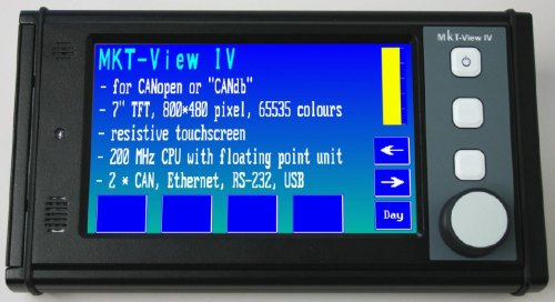
- MKT-View IV, with Landscape and Portrait mode
- Screen resolution 800 * 480 or 480 * 800 Pixel, 7"-TFT with 65535 colours (16 Bit/Pixel).
Funktionalität similar to MKT-View II/III, but faster CPU, and significantly larger.
- MKT-View V, with Landscape and Portrait mode
- Successor to the MKT-View III with similar size but much faster CPU,
and at least one CAN FD capable interface (details were unknown in 09/2019).
- UPT 320 "Color":
-
Screen width=320, height=240 Pixel, 5.7" TFT with 65536 different colours
(16 bit / pixel), touchscreen, rotary encoder button, ARM CPU, keyboard with
6 (?) keys.
Replacement for the discontinued "UPT 167 color". Firmware available for raw CAN / CANdb (#11352) and for CANopen (#11353) .
- UPT 800:
-
7" - Display panel with 800 * 480 pixel ("WXGA") TFT, 65536 colours (16 bit
/ pixel), Touchscreen, but neither rotary encoder button nor keyboard.
Designed for panel mount. So far (2011-11), only available as prototype with "CANdb". Firmware #11372 (for Controller type LPC2478, ARM-7, not ARM-11).
-
If a standard device (with standard firmware!) is used, the programming tool
will know everything it needs to know about the target from an internal
database.
All these settings are updated when selecting Options...Device Selection
/ LCD settings from the tool's main menu.
See also: Feature matrix (for various targets), Settings (tab), supported graphic functions (dialog), Table of Contents
Communication Channels
This page is used to define the communication channels which the terminal uses to exchange data with other devices on the CANopen network.
There are different types of communication channels:
-
SDO channel (Service Data Object)
a "slow"device-to-device connection which allows to exchange data from a device's object dictionary. Many different objects can be accessed through a single SDO channel ! -
PDO channel (Process Data Object)
a "fast" communication channel which is used to transfer process data with a high priority, for example digital inputs, analogue values from sensors etc. -
'Signals' defined in a
CAN-file
This optional functionality is only implemented in the programming tool for terminals with CANdb-functionality and therefore not explained here.
Details about variables connected to generic CAN signals ("CANdb"-signals) are here .
The type of a communication channel is implicitly defined by a variable's channel number (if it is connected to a communication channel).
Note that the terminal should only "listen" to PDO channels. It can not request the transmission of a PDO from another device (because this may cause a lot of trouble ...)
You have to define at least one communication channel for every device that the terminal shall communicate with. The channels will later be used to transfer values from other devices into the variables of your terminal program.
related topics: Variables on SDO channels , Variables on PDO channels , Receiving CAN messages which are neither connected to 'variables' nor 'signals' .
return to the table of contents
SDO Channels
- Note:
- SDO channels are not supported by the MKT-View terminals with 'CANdb' !
Only for a few devices (like MKT-View II,III), there is also a firmware variant which supports CANopen.
SDO channels provide a versatile but "slow"device-to-device connection which allows to exchange data from a device's object dictionary.
You have to define the CAN-identifiers of all SDO-channels which the terminal shall use to communicate with other devices. You can do this later with a CANopen configuration tool (if you have one), or in the SDO-channel table:
You will find the Identifier values in the description of the device that transmits a particular PDO or in the CANopen Draft Standard 301 (CiA "DS301"). Most I/O-devices use a "pre-defined connection set" with the following definitions for the SDO's CAN-Identifier (which DS301 calls "COB-IDs").
SDO(server->client) : CAN-Identifier = (1408+node-ID) = 1409...1535
SDO(client->server) : CAN-Identifier = (1536+node-ID) = 1537..1663
All CAN-Identifiers here are decimal values. The "client->server"-ID will be transmitted from the client (which is the UPT) to the server (which may be an I/O-module) to initiate a transfer ("request"). The "server->client"-ID will be transmitted from the server to the client (as "answer"). If you prefer hexadecimal notation for the CAN-IDs, you can change this on the ID format panel.
Hint: If you erase all cells in the above table, only enter the server node ID's, and click "Apply" afterwards. The tool will then fill out the missing CAN ID fields according to the predefined connection set specified in CANopen DS301.
- Always be aware:
- An SDO connection is just a "point-to-point" link between two partners. You must take extra care to use only SDO connections that are not yet occupied by other devices. If a simple I/O-device only has one SDO channel and this SDO is already occupied by an other device (maybe a PLC, SPS, a servo drive or something else), you must not connect the UPT to this device via "active" SDO request because this would cause severe collisions on the network (same CAN-ID transmitted by several devices, SDO protocol violations etc.).
In the User Programmable Terminal, a variable can be connected via SDO to an other device in the network. With the newer "MKT-View with CANopen" and other (newer) UPT's with 16-Bit-CPU it is possible to read values through the build-in SDO client via interpreter function "sdo(<index>.<subindex>)", without using a variable.
See also:
- Variables on SDO channels
- The CANopen Object Dictionary (one of the key elements of CANopen!)
- CANopen object index and subindex
- Using SDO channels (clients) in the script language: cop.sdo, cop.sdo2
- EDS files (electronic device specification)
- Features for devices with 'CANopen V4' (applies to most devices by MKT with CANopen and a 32-bit CPU) .
PDO Channels
- Note:
- PDO channels are not supported by the "CANdb" terminals (CAN without CANopen) !
PDO channels provide a "fast" communication channel that is used to transfer process data with high priority, for example digital inputs, analogue values from sensors etc. One PDO telegram can carry different parameters (if the transmitting device allows "variable PDO mapping"). More info can be found in the CANopen standard published by CiA.
In contrast to SDO-Channels, a single PDO-channel is always a one-way-street where the flow of traffic cannot be reversed during operation.
The following table is used to define all PDO channels ("RX" and "TX"):
For any PDO channel that you want to use in your application, you have to define:
-
the CAN-Identifier used by the PDO (sometimes
called "COB-ID"),
can be set to the default value (according to DS 301) with the button 'Default IDs'.
Use the button labelled 'Communication..', or double-click into the 'CAN-ID' column to open a Dialog to modifiy the PDO Communication Parameter - it may be easier for you to pick the values from a dialog instead of entering them in the PDO table. - the transmission direction (transmit, receive or "be passive")
- the transmission type as it is defined by the CANopen-standard. Similar as for the 'COB-ID' (CAN-ID), it may be easier to use the PDO Communication Parameter dialog to pick one of the quite 'cryptic' PDO transmission types.
- the transmission cycle ,
- and –possibly- some flags to activate "special" PDO functions .
In the (old) User Programmable Terminals like UPT515, a variable should be used to receive values from a PDO channel, or to put some data bits into a PDO which will later be transmitted, depending on the PDO‘s transmission type.
In the (newer) UPT II (like UPT320, UPT800), there are special variables in the CANopen Object Dictionary, which solely exist to be mapped into PDOs. They can be accessed from the application through their CANopen-index and -subindex (using the obd()-function), or be tied to interpreter variables. Because these variables do always exist, they are listed in the terminal's EDS-file, and can therefore be used by any CANopen configuration tool to setup the PDO communication in the network. More on that in the document about CANopen "V4" .
Be careful when tansmitting PDOs on a CAN-network which you do not know exactly ! Transmitting a PDO with the wrong identifier may cause a minor catastrophy - just imagine what would happen if you accidentally started an electronically controlled motor which *should* be off...). For this reason, the UPT was originally not able to transmit CAN messages, but "receive only" (this limitation had to be removed when someone wanted to use the UPT515 as a kind of PLC). Usually a CANopen device configurator / network configuration manager is used to configure "everything" in the network, including the process data channels. In newer devices with CANopen V4 (see Feature Matrix) the PDO's are controlled exclusively through the PDO communication- and mapping parameters, which are part of the standardized CANopen communication profile. So these parameters can be accessed from any CANopen configuration tool, after you loaded the application into the terminal. More information on this can be found in an extra document.
In a CAN network it is not allowed that more than one device transmit the same CAN identifier. Therefore the terminal should only "listen" to a PDO channel.
With the old UPT515 (since September 2001), it was possible to modify some of the PDO channel definitions with the UPT's interpreter. See PDO-Functions .
For terminals with CANopen V4 (since April 2005, see feature matrix), the PDO parameters can NOT be modified through the interpreter - instead, they can only be controlled through the terminal's local CANopen object dictionary !
See also:
- variables (of the interpreter)
- variables on PDO-channels
- channel number of a variable (which defines the type of the communication channel, too)
- fixed-type variables in the CANopen object dictionary of the terminal ("CANopen V4" only), which can be accessed through the function obd(<index>.<subindex>) .
PDO CAN Identifiers
You have to define the CAN-identifiers of all PDO-channels which the terminal shall receive. Identifier values can be found in the description of the device that transmits a particular PDO or in the CANopen Draft Standard 301 (CiA "DS301"). Most I/O-devices use a "pre-defined connection set" with the following definitions for the PDO's CAN-Identifier (which DS301 calls "COB-IDs").PDO1(tx) : CAN-Identifier = (384+node-ID)10 = 385...511
PDO1(rx) : CAN-Identifier = (512+node-ID)10 = 513...639
PDO2(tx) : CAN-Identifier = (640+node-ID)10 = 641...767
PDO2(rx) : CAN-Identifier = (768+node-ID)10 = 769...895
All CAN-Identifiers here are decimal values. Note that "tx/rx" in this table has to be seen from the I/O-devices point of view, so the "tx" PDO's are transmitted by an I/O-module and can be received by the UPT. The possible values for node-IDs are 1..127. Simple devices like I/O-Modules often use a DIP-switch to set the node-ID.
- Example:
-
You want to receive the state of digital inputs of an I/O-Module. The I/O-Module
uses its PDO1(tx) to transmit process data, which contain the digital inputs.
The node-ID of the I/O-Module is set to "1", so the resulting CAN-Identifier
will be (384+1)=385(decimal).
To receive this PDO with the UPT-Terminal, you want to use the first PDO-channel of the UPT. Just enter the value "385" in the column "CAN-ID of PDO". The UPT is now able to receive a PDO with this identifier, and you may define variables that use the PDO data as "input values".
- Note:
- Changing a CANopen device's node-ID shall affect the
PDO CAN identifiers, according to the 'predefined connection set' specified
by CANopen CiA "DS301". If your applications requires
a different CAN identifier for a certain PDO, first change
the node-ID (which resets most CAN-identifiers to the defaults),
and after that modify the CAN-IDs on the 'Channels' tab under 'PDO',
as shown in the screenshot further above.
This is always necessary if two (or more) CANopen slaves shall exchanged data via PDO directly, without a CANopen master (-> "PDO Linking") .
PDO Transmission Direction
Since the year 2000, displays with CANopen supports Reception and Transmission of PDOs. Therefore you have to specify, if a PDO channel shall receive(1), transmit(2) or be passive(0). For devices with CANopen V4 (since 2005), the transmission direction is fixed for all PDO channels like in an ordinary CANopen device. See feature matrix .
Note: "Transmit" and "Receive" must be seen from the UPT's point of view.
PDO Transmission Type
Since 2000, displays with CANopen support different types of PDO transmission.
The PDO transmission type is defined by a numerical value. It is taken from CiA DS301.
You may find more information on this in CiA Draft Standard 301, Version 4.0 (16.6.1999), Page 9-83 in the description of Objects 1400h-15FFh (PDO Communication Parameter), Table 54, "Description of transmission type":
| PDO Transmission Type |
Cyclic |
Acyclic |
Synchronous |
Asynchronous |
RTR only |
| 0 | X | X | |||
| 1-240 | X | X | |||
| 241-251 reserved | |||||
| 252 | X | X | |||
| 253 | X | X | |||
| 254 | X | ||||
| 255 | X |
A transmission type of zero means that the message shall be transmitted synchronously with the SYNC object but not periodically (?????).
A value between 1 and 240 means that the PDO is transferred synchronously and cyclically, the transmission type indicating the number of SYNC which are necessary to trigger PDO transmissions/receptions.
The transmission types 252 and 253 mean that the PDO is only transmitted on remote transmission request. The UPT515 treats both 252 and 253 exactly the same way.
Transmission type 254 is "manufacturer specific" (which is not defined yet).
Transmission type 255 is "defined in the decive profile" (which does not exist here).
For transmission types 254 and 255 you can use a PDO's Event Timer for cyclic
(but not sync-related) transmissions. See transmission cyclePdo_TxCycle.
Since August 2013, the PDO transmission type can also be modified in a special
PDO Communication Parameter dialog.
PDO Transmission Cycle
The PDO transmission cycle can be used for cyclic PDO transmission without a SYNC object.This works similar like a PDO's event timer as described in CANopen DS301 V4.0, see description of object 0x1400 subindex 5.
Note: Since September 2001, a PDO's transmission cycle can also be reprogrammed at runtime with the UPT interpreter.
Only for the old "UPT515": Special PDO Channels
Only the last PDO channel can be configured to be a "System State PDO" by setting the FLAG value to "1".The "System State PDO" has the following contents:
- Byte[0] = UPT run mode (e.g. 1 = "running")
- Byte[1] = digital Inputs of the UPT
- Byte[2] = current display page of the UPT
- Byte[3] = Key-Matrix[0], the "first" 8 keys of the keyboard driver.
- Byte[4] = Key-Matrix[1], the "next" 8 keys of the keyboard driver.
You should leave all flags "zero" to use flexible TX-PDO-Mapping from Variables.
Again, the fixed 'system PDO' described above only exists in the old "UPT515"
with 8-bit CPU. All newer, user-programmable CANopen terminals (with 16-
or 32-bit CPU) use flexible PDO mapping so we don't need this 'fixed' mapping
anymore.
(On this occasion: Early samples of the UPT128 used a membrane keyboard
labelled 'UPT515', but in fact the UPT128 is not a UPT515: It has a modern
32-bit CPU inside, not a stoneage 8051-compatible controller).
PDO Mapping
In CANopen, 'PDO mapping' basically means 'defining the contents of a PDO telegram' (CAN frame carrying process data).Due to the complexity of CANopen, the documentation was moved into a separate document.
Generic CAN Channels ("CANdb")
'Generic CAN Channels' only exist for devices without CANopen. These channels are used to exchange communicate with external devices via CAN/CAN FD/LIN (but, again, 'without CANopen'). Definitions of whatever can travel over such a channel is usually imported from a 'CANdb'-file or (planned for future devices) from an AUTOSAR database.This optional functionality is only implemented in the programming tool for terminals with CANdb-functionality and therefore not explained here (but in an extra file - follow the link for details).
Application Variables (display interpreter variables)
The tab sheet "Variables" of the programming tool is used to define all variables which the terminal will use to show and modify parameters.All variables are defined in a table, their properties can be edited in the table or on a special property panel.
Most of your variables will be connected to a communication channel, but they can also be used as internal variables which keep temporary values etc.
Notes:
- All "display variables" can be accessed by the display-interpreter, which means a variable name can be a part of a numeric expression.
- The name of a variable must always begin with an upper-case letter, and it may never have more than 8 characters. Only in certain devices with CANdb functionality up to 16 characters may be used (see constant parameter "max var name length" under Settings).
- The above limitation does not apply to script variables ! Script variables are not defined on the tabsheet 'Variables'. Instead, they are declared the script sourcecode.
- To assign a new value to a variable during run-time, use the assign command ("@"). This only makes sense for ('display'-) variables which do not receive their values from a communication channel.
- To show the value of a CANopen object on the screen, you don't need to connect it to an application variable. You can access any CANopen object (inside the device's own CANopen object dictionary) by its CANopen index and -subindex ( obd(index.subindex) ).
Related topics:
- Connecting variables to display lines with a special dialog
- Communication Channels
- Variables on SDO-Channels (only for certain terminals)
- Variables on PDO-Channels (only for certain terminals)
- Variables linked with objects in the terminal's own CANopen OD
- Variables on CANdb-SIGNALS (only for certain terminals)
- CANopen object index and -subindex
- Variables as part of a numeric expressions for the interpreter
- Components of a variable which can be accessed via interpreter
- fixed-type, fixed-index CANopen variables (only for devices with CANopen V4)
- Inspecting variables remotely, using an internet browser (only for devices with ARM-CPU)
- Finding all references to a variable (in global events, local events, display pages, etc)
- a href="scripting_01.htm#variables">script variables
Properties of display variables
You can define all display variables in the table shown below, on the 'Variables' tab in the programming tool.Script variables are not defined here, but in the Script sourcecode.
Network variables are a subset of display variables, using definitions imported from a DBC file ("CANdb"), or which (for CANopen devices) can be accessed via SDO, PDO, etc.
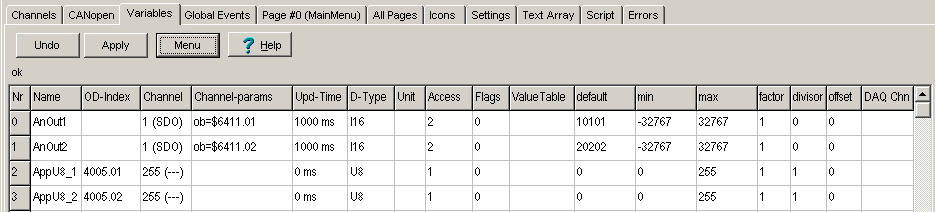
(Example of a table with variable declarations; here for CANopen)
- Name : Up to 8 characters for small systems (like UPT515), otherwise up to 16 characters
-
OD-Index : Only for CANopen; non-empty means this variable is connected to
one of the objects
in the terminal's own CANopen object dictionary. Details here . -
Channel : Defines if
and how a variable is connected with the outside world :
0...4 = SDO client (CANopen), 5...9 = SDO server (CANopen), 10..19 = PDO (CANopen),
30 = connected to a so-called signal which is defined in a DBC-file ("CAN per database", not CANopen)
31...99 = reserved for future communication channels (device specific)
100...149 = reserved for devices which have more than 5 CANopen SDO clients
150...199 = reserved for devices which have more than 5 RPDOs (Receive-PDOs)
200...249 = reserved for devices which have more than 5 RPDOs (Receive-PDOs)
250...254 = reserved for future, "exotic" communication channels
255 = this variable is not connected to the outside world (it only exists "internally").
The programming tool automatically shows the meaning of the numeric code in the definition table. - Channel-params: PDO / SDO / CANdb_signal_definition (channel type specific)
- Update Time (or "cycle time" for CANdb-signals)
- Data Type: Should be modified only for 'internal' variables !
- Unit (only for CANdb, where physical units are defined in a database)
- Access Rights: 0=read only, 1=read/write, 2=write only
- Flags: Automatically filled in by the tool (where applicable)
-
Value Table: May have been imported from a CAN database. Certain 'special values'
may be displayed as one of these strings instead of a numeric value
(e.g. "SNA" = "Signal Not Available" instead of 255 for an 8-bit signal).
Syntax:<decimal value 1>=<display string 1>,<decimal value 2>=<display string 2>, ..
Example:255=SNA,0=off,1=idle,2=normal,3=max dry,4=max reheat,5=combat
To show the matching entry in a value table (instead of e.g. a decimal number), set the display element's numeric base to ZERO (='automatic', which means 'if there's a value table, show the matching entry if possible, otherwise show the value as a decimal number); instead of Base = 10 (which means 'always show the value as a decimal number').
If necessary, a variable's value table can also be edited in the programming tool instead of modifying it in the CAN database (which would include re-importing the modified database). To edit the value table, double-click into the cell in the 'Value Table' column. This opens an editor with one value/text pair per line, which makes editing items easier than editing the long string of value=text pairs in a single cell of the 'Variables' definition table.
The value-table editor shows the decimal value on the left side, and the display text on the right.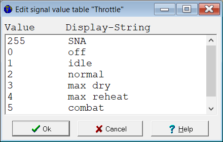
See also: Details about signal value tables from CAN databases and the 'decoding process'.
- Default Value
- min, max: Limit the value for display and editing (on screen).
-
factor, offset, divisor: Used to convert the value sent via CAN-bus into the physical value.
Do not modify these parameters manually; they are usually taken from a database (CANdb) ! - DAQ channel number (DAQ = data acquisition unit; optional; details here )
During the simulation (in the programming tool), the current values can also be displayed
in an extra column of the definition table. To activate this option, check
Show current values in the table (last column) in the context menu.
Alternatively, a variable's current value can also be inspected by
hovering over the variable name with the mouse
as in most other definition tables.
Most properties of a variable can be modified on this "property"-panel:
Some properties (components) of a variable can also be accessed during run-time
of the terminal application from the UPT's
interpreter.
Udate-Time of a variable
The update time of a variable defines, how often a variable will be updated from its input channel.For example, a variable may be connected to an analogue input of an I/O-module via SDO, and the Update-Time is set to "500".
In this case, the Terminal will send a "read request"-telegram every 500 ms via SDO to the I/O-module. As soon as the I/O-module answers with a "read response"-telegram, the new value for the variable is taken from the response and converted into a 32-bit-value for the variable.
- Only for variables which are connected to CANdb-"signals":
- Here the 'update time' has the meaning of a 'transmission cycle time'.
In old devices (like MKT-View "Plus"), the cycle time also affected the strategy for allocating message-objects in the 'Full CAN' controller.
For transmitted CAN signals (from the MKT-View's point of view), the 'Upd-Time' parameter defines the transmit cycle (for periodically transmitted CAN frames).
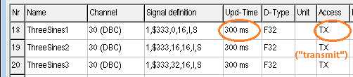
If necessary, the transmit cycle can be modified at runtime as in the following examples:
(Source: Test/demo application ?/programs/CdbSendT.cvt, page 4)ThreeSines1.cy := 0; // Turn off periodic transmission ThreeSines1.cy := 300; // Periodically transmit every 300 ms
Data-Type of a variable
The data type of a variable defines the internal storage format and the legal value range (if it is a numeric variable). The UPT only supports numeric data types from the CanOpen-Standard. Floating point values are only supported by terminals with 32-bit CPU (ARM-7 or Cortex-M, for example MKT-View II / III). Most values are internally converted into signed 32-bit integer values (which is the "internal" storage format for all variables and expressions inside the UPT).Data types used in the Variable Definition Table use CANopen data types, even if the terminal itself doesn't support CANopen.
| Indicator / Type Name |
Code (as defined in CANopen) |
Data Type ( as defined in CANopen) |
Remarks |
| UNKNOWN | 0 | unknown | |
| BOOL | 1 | BOOLEAN | |
| I8 | 2 | 8 bit SIGNED integer | |
| I16 | 3 | 16 bit SIGNED integer | |
| I32 | 4 | 32 bit SIGNED integer | |
| U8 | 5 | 8 bit UNSIGNED integer | |
| U16 | 6 | 16 bit UNSIGNED integer | |
| U32 | 7 | 32 bit UNSIGNED integer | |
| F32 | 8 | 32 bit floating point | not supported by some devices |
| STR | 9 | "visible" string ("printable" string of characters) | |
| OCT | 10 | Octet string (a CANopen speciality ! ) | not supported by any device |
If a variable is connected to a CANdb signal, the programming tool may show 'S' (signed) or 'U' (unsigned) instead of the codes shown above. But internally, any received signal is internally converted into the best fitting data type listed in the table above.
The even more exotic data types mentioned in the CANopen standard DS301 (like "time of day") are not supported by the programmable terminals.
Notes:
-
UPT515: Variables which are connected to CANdb signals may be handled as
floating point values internally. The mantissa only contains ~~24 bits.
Values like 1000000.05 cannot be stored in this kind of "short"
floating point variables !
-
You can determine the (CANopen-compatible) data type of a variable at
runtime using the "ty" property ("type").
- To convert a numeric data type code (a la CANopen) into a human-readable string, use the function type2str() (type-to-string) .
Access Rights of a variable
The property "Access Rights" of a variable defines if it can be read and/or written via communication channel.- For example:
- A variable is connected to an analog output of an I/O-module via SDO, and you want to set the voltage of that output with the terminal. After assigning a new value to the variable (by editing it or by assigning a value with the assign-command), the terminal will send a "write request"-telegram via SDO to the I/O-module to update the output. The variable must be writeable for this purpose.
A "read-only"-Variable will never be transferred to an external device via communication channel.
A "write-only"-Variable will never be read from an external device via communication channel.
With a few exceptions (for CANdb) below, the access-rights of a variable are coded as numeric values according to the CANopen-Standard.
- Possible values are in this case (CANopen):
-
0 = Read Only
1= Read/Write
2 = Write Only
For variables connected to CAN signals, the
column "Access" in the variable definition table shows if the signal is receved
or transmitted from the terminal's point of view.
(Reception is the normal case, Transmission will only be
possible with new firmware since November or December 2009) .
- Possible "Access" values are, in this case (CANdb):
-
RX = The terminal receives this signal from the network (and all other signals
contained in the same CAN-message !)
TX = The terminal transmits this signal into the network (and all other signals contained in the same CAN-message !)
In contrast to CANopen, combined read/write access (as in CANopen) is impossible in this case,
because a CANdb file doesn't specify any protocol for that !
These values can also be seen in the combo box on the variable's 'property' panel .
Finding all references to a variable, function, signal, string, etc (globally)
In complex display applications, you may ask yourself where a certain variable is used, or if it is still in use anywhere at all. One possibility is to simply search for its name in the display application (*.upt or *.cvt) with a text editor.An alternative is to let the programming tool search for all references of a display variable. The variable-search is a available in the context menu of the variable definition table:
- Click into the variable definition table on the name of the variable (here: Tank1Level).
- Click on the 'Menu' button above the table, or click into the table with the right mouse button
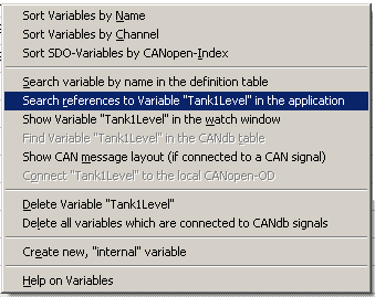
(screenshot of the context menu for the variable definition table)
- all global event definitions, in both the 'Event', and the 'Reaction' column;
- all local event definitions, on all pages;
- all display definition lines, also on all pages;
- all lines of the Script Editor (where such variables are prefixed by the keyword 'display.');
- all definition lines of the CAN simulator (with signal definitions and 'Conditional Actions').
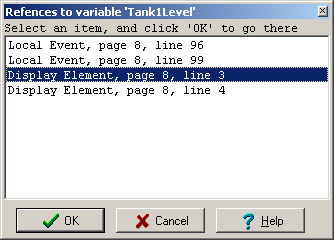
(screenshot of the 'search variable reference' result window)
In contrast to the search for variable names, the global text search ignores quotation marks, and can thus be used to find any test, even in double-quoted string constants.
Click on any of the result lines to switch to the event / display line definition where the variable is used (or where the text was found).
This can give you a quick overview about the usage of certain variables, and look for orphaned variables (variables which are not in use anymore).
To close the modal dialog window, click 'Ok' or 'Cancel'.
The search results are also displayed as plain text on the error page ( → 'Errors & Messages'), from where they can be copied for documentation. A double- or right-click on a search result on the error page also switches to the place where the text was found (display page, script line, etc). Thus, switch between the 'Script' and 'Errors' tab to toggle between the the script sourecode and the list of search results.
A similar 'global search' (on all pages, in all event definitions, etc) can also be invoked from other context menus, e.g. from the page-definition table, event-definition-tables, CAN simulator signal definition table.
back to the overview of Application Variables
See also: Declaration of Script Variables .
Variables on SDO channels
- Note:
- SDO channels are not supported by the MKT-View terminal (CANdb only)
A variable can be "connected" to an object in an other device in the network via SDO channel.
The "objects" of a CANopen-device are located in a so-called dictionary. Every object of this dictionary is defined by its Object-Index and Subindex .
These parameters are defined on the following panel, which will be visible if the current variable is connected to an SDO-channel:
To "connect" a variable to an object of a CANopen-device, you have to define:
- the SDO channel number (which connects the UPT to a certain device)
- the index and subindex of the CANopen object
- the data type of the object
- the access rights (i.e. "read only")
See also:
- Channel number of a variable (which also defines the channel type, like SDO-client, SDO-server, etc)
Variables on PDO channels
- Note:
-
This chapter only applies to older terminals, with a very old CANopen version.
In newer terminals, only objects in the
CANopen-OD can be mapped into a PDO.
In terminals with "CANdb" (CAN without CANopen), PDO channels are not supported at all !
The input of a variable can be connected to a part of a PDO channel (a PDO can carry up to 8 bytes of information, and you will usually only use a part of that data field).
To "connect" a variable to a PDO channel, you have to define:
- the "UPT-internal" number of the PDO channel
- the number of data bits that shall be transferred from the PDO into the variable
- the number of the fist data bit in the PDO (which is the least significant bit)
- the data type of the object
These parameters are defined on the following panel, which will be visible if the current variable is connected to a PDO-channel:
Notes:
- In the "UPT-2" (with CANopen V4, like "UPT320"), it is not possible to map interpreter variables directly into a PDO. In those cases, you must use the PDO-mappable variables in the terminal's CANopen-Object Dictionary, instead of mapping the old self-defined variables into a PDO ! To access those variables from the application, use the interpreter function obd(<Index>.<Subindex>) , or connect the CANopen-objects with interpreter variables as explained here . Those special variables have the big advantage of being defined in the terminals EDS-file (in contrast to the self-defined variables), so they are recognized by any CANopen configuration tool - which greatly simplifies the configuration of the network !
- only 1-bit-parameters can be read from any bit-position in the PDO.
- 8-, 16-, 24- or 32-bit-Parameters must start on a BYTE boundary in the PDO data field, so the "number of the first bit in the PDO" must be a multiple of 8. The bit-count starts at 0 (ZERO) not 1(ONE), in contrast to some strange programming languages.
- Parameters with more than 8 databits are always transferred in "low to high-byte-order".
- The UPT simulator does not support PDO functionality, because the PC's CAN-Interface is just a BASIC-CAN-Controller.
Related topics: communication channels , SDO channels , PDO channels , channel number of a variable
Variables connected to the terminal's "own" CANopen object dictionary
In recent devices (with 32-bit CPU), only certain objects from the CANopen OD can be mapped into a PDO, making it impossible to directly map interpreter variables into PDOs. The interpreter can access all objects in the terminal's own object dictionary (using the obd function), but accessing data by hexadecimal indices is not everybody's taste. For that reason, certain CANopen objects can also be linked with an interpreter variable. Each read-access to the interpreter variable then actually reads a CANopen object, and each write-access modifies that object. If the object is mapped into a PDO, the CANopen protocol will possibly update (or send) the PDO.To make things easier, you don't need to remember which objects can be used for that purpose. Instead, double-click into the column titled OD-Index in the variable definition table (or press ENTER while a cell in this table is selected) :
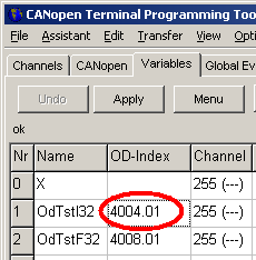
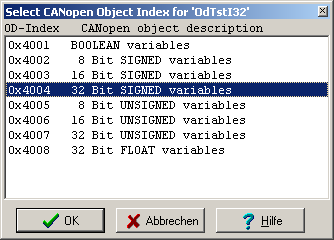
- Hint:
- If you are familiar with CANopen, you will have noticed that these indices are simply 0x4000 plus the CANopen data type code, for example code "4" means 32-bit signed integer.
If no CANopen object had been connected before starting the dialog, the program may decide to select an object which matches the variable's data type as close as possible (if enough unused subindices of such an object are remaining). Each object has 10 or 40 subindices, depending on the terminal firmware (option "Monster-OD" only available for devices with 32-bit CPU), resulting in a grand total of 360 individual values which can exist in this part of the OD. Unfortunately, because the CANopen-OD is 'static', these dimensions cannot be changed.
The programming tool will try to pick the next unused sub-index of the object automatically. You can see (and edit) the subindex after closing the dialog box with "Ok" .
Interpreter variables connected with the CANopen object dictionary are always visible to 'the outside world', because a CANopen configuration utility may map it into a PDO (even if you didn't map it in the UPT programming tool). Furthermore, such objects can always be accessed via SDO, if an external SDO client knows the OD-index and -subindex. For CANopen, such external connections are usually configured with a special utility (for example with the CANopen Configuration Manager, which doesn't just configure a single CANopen node, but an entire CANopen network). During normal operation ("operational state"), only PDO will be used between CANopen slave devices, because the few SDO servers in most CANopen slave devices are reserved for the CANopen master, and thus cannot be used by other devices.
Back to the overview of an interpreter variable's properties .
- (*)
-
Unfortunately, these objects in the CANopen-OD cannot have 'talking' names,
because the name of CANopen objects is not variable (at least not in the
EDS file). For this reason, you will
only find such general, unspecific names like "Application Vars 32 bit signed"
for object 0x4004 in the EDS file.
To simplify using the display terminal as CANopen slave in combination with external PLC software (like z.B. CoDeSys), the UPT programming tool (2) can generate a DCF (device configuration file), which will then contain the "talking" names (i.e. the name of the variable, if a variable is connected to a certain CANopen object in the display's own CANopen-OD). The UPT VARIABLE NAMES will appear as Denotation in the DCF. Details about the DCF-Generator are here .
Usage of "index" and "subindex" for SDO variables
For a variable which is connected to an SDO channel, you have to define an index and a subindex.The "objects" of a CANopen-device are located in a so-called dictionary. Every object of this dictionary is defined by its Object-Index and Subindex.
The Object-Index is a 16-bit-number which is usually defined in hexadecimal format. In the terminal programming tool, hexadecimal numbers begin with the "0x" or "$"-prefix, otherwise the interpreter would treat them as decimal numbers.
The Subindex is an 8-bit-number which is often used for arrays or structured objects.
For example, a DS401-type module with 5 digital inputs may have an Object 0x6020 which contains the state of the digital inputs. Subindex 0 of this object will have the content "5" to indicate that there are 5 digital inputs, subindex 1 will hold the actual state of the first digital input, subindex 2 the state of the second input and so on.
Index and Subindex of CANopen-Objects are often defined in a device's manual. But for many objects you may also find the required information in a so-called DeviceProfile . There are device profiles for different types of CANopen-devices, for example:
DS401: Device Profile for I/O Modules
- digital in- and outputs
- analog in- and outputs
DS401, Digital In- and outputs
DS401 specifies the CANopen Device Profile for I/O-Modules. If you want to connect any of these objects via SDO to a variable of your terminal program, you have to know the object's index and subindex (or have an EDS file..).Here are some of the specified objects:
Digital Inputs and Outputs
| Index (hex) | Name |
Subindizes |
Type |
Access |
| 0x6000 | Read State [of] 8 Input Lines | 0,1 .. max.4 | Unsigned8 | ro |
| 0x6006 | Input Interrupt Mask [for] 8 Input Lines, any change | 0, 1.. max.4 | Unsigned8 | rw |
| 0x6020 | Read State [of] 1 Input Line | 0, 1.. max.32 | Unsigned8, Boolean |
ro |
| 0x6100 | Read State [of] 16 Input Lines | 0, [1, 2] | Unsigned16 | ro |
| 0x6120 | Read State [of] 32 Input Lines | 0, max. 1 | Unsigned32 | ro |
| 0x6200 | Write State [for] 8 Output Lines | 0, 1..max.4 | Unsigned8 | rw |
| 0x6206 | Fault Mode [for] 8 Output Lines | 0, 1..max 4 | Unsigned8 | rw |
| 0x6207 | Fault State [for] 8 Output Lines | 0, 1..max 4 | Unsigned8 | rw |
| 0x6220 | Write State [for] 1 Ouput Line | 0, 1.. max.32 |
Unsigned8, Boolean |
rw |
| 0x6250 | Fault Mode [for] 1 Output Line | 0, 1..max.32 |
Unsigned8, Boolean |
rw |
| 0x6260 | Fault State [for] 1 Output Line | 0, 1..max.32 |
Unsigned8, Boolean |
rw |
| 0x6300 | Write State [for] 16 Output Lines | 0, 1..max.2 |
Unsigned8, Unsigned16 |
rw |
| 0x6306 | Fault Mode [for] 16 Output Lines | 0, 1..max 2 |
Unsigned8, Unsigned16 |
rw |
| 0x6307 | Fault State [for] 16 Output Lines | 0, 1..max 4 |
Unsigned8, Unsigned16 |
rw |
| 0x6320 | Write State [for] 32 Output Lines | 0, max.1 |
Unsigned8, Unsigned32 |
rw |
| 0x6326 | Fault Mode [for] 32 Output Lines | 0, max 1 |
Unsigned8, Unsigned32 |
rw |
| 0x6327 | Fault State [for] 32 Output Lines | 0, max 1 |
Unsigned8, Unsigned32 |
rw |
DS401, Analog In- and outputs
DS401 specifies the CANopen Device Profile for I/O-Modules. If you want to connect any of these objects via SDO to a variable of your terminal program, you have to know the object's index and subindex. Here are some of the specified objects:Analog Inputs and Outputs
| Index (hex) | Name | Subindizes | Type | Access |
| 0x6401 | Reads value of the input
channel (not converted) |
0
1 [... 4] |
Unsigned 8
Unsigned16 |
ro |
| 0x6411 | Writes value of the output channel (not converted) | 0
1 [... 4] |
Unsigned8
Unsigned 16 |
rw |
| 0x6420 | Set Analogue Input Range |
0
1 [... 4] |
Unsigned8
Unsigned 16 |
rw |
| 0x6421 | Determines which events cause an interrupt for a specific channel | 0
1 [... 4] |
Unsigned 8
Unsigned 8 |
rw |
| 0x6423 | Globally enable/disable Interrupt | 0 | Boolean | rw |
| 0x6424 | When enabled, interrupt triggered when analogue input rises above this value (not converted) | 0
1 [... 4] |
Unsigned8
Unsigned 32 |
rw |
| 0x6425 | When enabled, interrupt triggered when analogue input falls below this value (not converted) | 0
1 [... 4] |
Unsigned8
Unsigned 32 |
rw |
| 0x6426 | When enabled, interrupt triggered when analogue changes by more than thisvalue from previous reading (rising or falling) (not converted) | 0 1 [...4] |
Unsigned8, Unsigned 32 |
rw |
| 0x6443 | Output Fault Mode | 0,1 | Unsigned8 | rw |
| 0x6444 | Default Output Fault value (unconverted) | 0
1 |
Unsigned 8
Unsigned 32 |
rw |
Variables connected to 'generic' CAN-Signals (described via *.dbc)
Only for certain terminals which support the reception
of signals defined in a CAN database (*dbc, Database for CAN) !
THIS IS NOT FOR TERMINALS WITH "CANOPEN-COMPATIBLE PROTOCOLS" !
Details about connecting variables with
"CANdb"-signals are in a different file .
<BusNr>,<CAN-Identifier>,<position of LSBit>,<number of databits>,<INTEL/MOTOROLA-flag>,<signal type>
where..- BusNr
-
may be 1 or 2, if the device has two physical CAN interfaces (e.g. MKT-View II/III/IV);
or 3 or 4, if the device supports CAN-via-UDP or LIN.
For MKT-View II / III / IV, "CAN1" and "CAN2" are labelled as such on the adapter cable (or, maybe, "KFZ-CAN1" / "KFZ-CAN2" as requested by some customer).
Those "Bus-Numbers" are usually set when importing a CAN database, because before selecting the database filename, the bus number is selected on tabsheet "CAN" in the tree view ("CAN1", "CAN2", ...), or by using button 'Load DBC #1' (for CAN1) or 'Load DBC #2' (for CAN2). If anything else fails (because the CAN database isn't available for you anymore), you can edit the bus number on tabsheet 'Variables', but the preferred method of selecting the bus number is importing the database for a certain bus.
- CAN-Identifier
-
= 3- or 8-digit hex number, depending on 11- or 29-bit identifiers for CAN messages
- position of LSB in CAN message
-
is explained in another document in detail.
For CAN and LIN, data bits in the payload are numbered from 0 to 63.
If we ever get hold of a microcontroller that properly implements CANfd, the numbers may be higher, but the principle ("start counting bits at zero") remains the same.
- Number of databits
-
is also explained in the other document
- Flag for INTEL- or MOTOROLA format
-
is what makes CANdb signal processing even more complicated ;-) ...
you already guessed it, details are in another document
I = "Intel" (aka little endian, least significant byte first)
M = "Motorola" (aka big endian, most significant byte first)
- Signal type ("raw signal format" on CAN)
- U = Unsigned (Signal wird auf dem CAN-Bus als vorzeichenlose Ganzzahl übertragen)
S = Signed (Signal wird auf dem CAN-Bus als vorzeichenbehaftete Ganzzahl übertragen)
F = Float (Signal wird auf dem CAN-Bus als 32-Bit-Fliesskommawert übertragen)
D = Double (Signal wird auf dem CAN-Bus als 64-Bit-Fliesskommawert übertragen)
Additional information may be contained in the definition for MULTIPLEXED signals.
Don't try to change the CANdb signal definition yourself here ! It is possible to define everything on the 'Variable' definition tab (and possibly your only chance if you don't have a CANdb file describing your network), but you better use the method described below (and in a separate document) .
The preferred method is to use an external CANdb file editor for this, and re-import the modified CANdb file as explained here. This will take you to the 'CANdb' tabsheet, where you can browse the database, and connect a few signals to display variables ('UPT interpreter variables') :
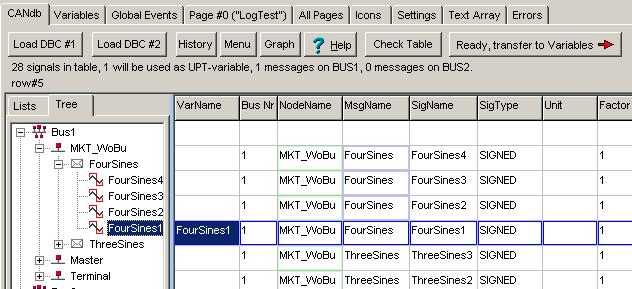
( CAN Database display; more details
here )
See also (concerning 'CANdb'):
- Basic principle to build a display application for CANdb-signals
- Timeout monitor function for CANdb signals
- Modifying the CAN-identifier of a variable connected to a CAN-signal 'on-the-fly'
- CAN Message Layout (display window, also available for variables with CAN bus connection)
- Overview of application variables
- CAN Message Generator / Bus Simulator
Variables connected to 'openABK'
.. only availble in german language, and will most likely never be translated because 'OpenABK' appears to be a dead horse.Data Breakpoints (to stop on assigning certain values to a certain variable)
For hardcore-debugging, the simulation may be paused on a write-access (assignment) of a certain value (or value range) to a certain variable. To define such a 'data breakpoint', switch to the 'Variables' tab, and right-click into the variable that you want to monitor. In the context menu, selectSet Data Breakpoint when assigning 'XYZ'
(where 'XYZ' is the name of the variable)
Next, enter a value range which (when assigned to the selected variable) shall pause the simulation.
When omitting the 'max' value (after the comma), the data breakpoint will only fire on a single value.
If the data breakpoint fires, the simulator will emit a message like the following on the Errors & Messages tab, including the variable's old and new value:
Data breakpoint fired on global event 12 when setting XYZ := 123.4 .
or (if the assignment wasn't in a 'Global Event' but on a certain display page):
Data breakpoint fired on page 13, line 14, when setting XYZ := 123.4 .
- Hint about the principle of data breakpoints (as implemented here):
- A data breakpoint defined this way behaves like an edge-triggered oscilloscope.
The "trigger" (in this case, pausing the simulation with message 'why')
only occurs if the old variable value was outside,
and the new value is within the value range defined
as described above. When setting (defining) a new data breakpoint,
the variable's current value is internally stored as 'old value'
to prevent false triggers.
gray : Breakpoint still 'passive' because it could not be evaluated yet (not running)
yellow : Breakpoint is 'armed', but hasn't fired yet
red : Breakpoint has fired, and the simulation has been paused.
Due to the data breakpoint being edge-triggered, the simulation can be resumed easily by clicking the panel showing 'Stopped' in the status line. It will not stop before the variable's value gets inside, and again outside the range defined for the data breakpoint.
Similar as after hitting a 'Code Breakpoint' (in this case, a breakpoint on a global or local event), the application can be examined in single step mode (using F11 for a single step) after being paused via data breakpoint.
Settings (on tabsheets and dialogs in the programming tool)
Parameters in the right part of the 'Settings' tab
The right part of the tabsheet titled 'Settings' is used to define parameters that do not depend on your terminal application - see next subchapters.Programming Tool Settings
The panel titled 'Programming Tool Settings' must be filled out by you matching your hardware configuration (CAN bus interface), and the current settings of your terminal (e.g. CAN baudrate):- Interface type and/or I/O-Port address of the PC's CAN-Interface
- CAN baudrate to establish a connection to the programmable terminal
(Note: There are additional CAN bit timing parameters, part of the User Settings, which only have an effect inside the programmable device) -
Serial interface (e.g. "COM1"): This was formerly used to download
the application into the terminal via RS-232 (utterly slow).
This port can also be used to connect a GPS mouse, to emulate devices connected to a GPS receiver in the programming tool.
If the programming tool detects a specific device on USB (by its USB Product Name), it may suggest to switch to the matching COM port as described in the chapter about Transfer / Connection via USB and 'Virtual COM Port'.
-
Serial Port Baudrate: Used by the programming tool, also during 'simulation'.
Note: Not all baudrates are supported by all devices !
Especially baudrates like 230400 and 460800 bit/sec will only work with suitable hardware (like USB adapters).
This baudrate is used for the normal program download via RS-232 (which is still possible, if the programmable device has such an interface), and also for the file transfer utility. - The terminal node ID affects the SDO-identifier of the programming tool (for CANopen, this must match the node ID of the device you are going to program)
- The 'simulated' node ID is used if the programming tool runs as a 'simulator', emulating a CANopen device with this ID
- Simulated sound: This combo defines if and how the device's audio output shall be emulated, e.g. "off" (no sound) or using the PC's soundcard with MIDI synthesizer
- Select help language: This item should speak for itself
- mark edited object in the simulator: See description of the LCD simulator
- Emulate embedded web server: Allows simulating the HTTP server (integrated in a few devices) on the PC). For details about the web server, follow this online line.
Because running a web server in a PC program may cause trouble with the PC's firewall, this option is disabled by default.
Besides the option 'emulate Embedded Web Server', the server's (TCP-)port number can also be modified on this panel. The port number (usually 80 for HTTP) only applies to the simulation on the PC ! The web server in the 'real' device (MKT-View) is configured in the device's 'Network-Setup'.
The 'TEST' button (right next to the port number) can be used to establish a connection to the server (running on the same PC, using the loop-back IP 127.0.0.1 . - Emulate embedded web server: Allows simulating the HTTP server (integrated in a few devices) on the PC). For details about the web server, follow this online line.
The 'Terminal Node ID' (for CANopen) and the CAN-Baudrate must match
the settings in the terminal, if you want to upload programs successfully via CAN.
Selection of disk folders (directories)
Below the 'Programming Tool Settings' you will find the 'Directories', which are used by the programming tool to store different kinds of files.
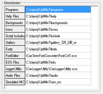
The adjustable directories / paths include...
- the directory in which you want to store your terminal applications (by default, this is the 'programs' folder),
- the directory which contains the help system in HTML format (you certainly never need to change this, in contrast to selecting a different HTML browser),
- the directory from which 'Icons' are imported by default (this can save a lot of time wasted in window's "file selector" dialogs),
- the directory for your own script include files,
- the 'fonts' directory,
- the directory where the optional font editor has been installed (so the programming tool can launch it from a menu),
- the directory where the optional CAN logger utility has been installed ( " " " .. ),
- the directory with wave audio files (used to simulate certain terminals with analog audio output capabilities),
- the directory for the simulation of the memory card, used to develop advanced applications (with file I/O via script) without a 'real' target hardware.
- Programming Tool for displays with 'CANopen' : C:\WINDOWS\MKT_CANopenTerminalProgTool.ini
- Programming Tool for displays with 'CANdb' : C:\WINDOWS\MKT_CANdbTerminalProgTool.ini
None of the programming tools by MKT uses the windoze registry to store important data.
Parameters in the left part of the 'Settings' tab
The left part of the 'Settings' tab contains two large tables labelled 'Terminal constants, settings, non-volatile values'. Both tables can be scrolled vertically because in most cases, their entire content doesn't fit on the screen.
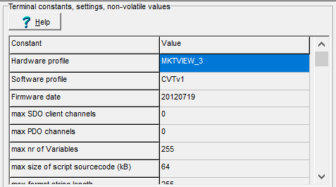
The next two sub-chapters describe the entries of the upper table ("Constants")
which describe the device, and the lower table ("Terminal Settings")
which configure the device.
Terminal constants (upper part of the tabular display)
The "Terminal Constants" cannot be changed (except for a few exceptions listed below), they are only displayed for your information. Because there is a large number of UPT firmware variants and versions out there, the UPT programming tool attempts to read this information from the terminal when a program is uploaded or downloaded. Some of the "Terminal Constants" are:- Hardware profile: Name of the target hardware, e.g. "MKTVIEW_3_Landscape".
You can click into this cell to select a different target device (also for the "Software Profile"). - Software profile: Explained in the description of the target selection dialog.
- Firmware Compilation Date (of the programmable device), important to avoid conflicts with 'old' firmware .
- (max number of) SDO channels
- (max number of) PDO channels
- (max number of) Variables
- maximum size of the script sourcecode (in kBytes, target specific, and unknown by the time of this writing)
- max length of a format string (also usable as static display text or as menu item)
- max length of an event "condition" definition (number of characters, usually 25)
- max length of an event "reaction" definition (usually 48 characters)
- max number of "global" events (usually 20)
- max number of commands per display page (usually 15)
- max number of display pages without "specials" (like text array and icons, usually 150)
- max length of a page name (usually 8)
- max length of a variable name (usually 8)
- max number of lines in the text array (usually 1024)
- max number of icons, limited by memory manager
- Flash memory management type (static/flexible)
- display type: 1=monochrome, 4=color with 4 bits/pixel
- display width: 128 pixels for UPT515 and UPT-Handheld, 320 for UPT320, "MKT-VIEW","IPE-VIEW"; 480 for "MKT-View II / III"; 800 for UPT800.
- display height: 64 pixels for UPT515 and UPT-Handheld, 240 for UPT320, "MKT-VIEW","IPE-VIEW"; 272 for "MKT-View II / III"; 480 for UPT800.
- Supported fonts as a bitwise combination for all font numbers.
As for some other parameters, click on this item to open a special dialog:
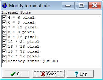
Dialog with a list of fonts supported by a certain device.
- plus a lot of 'other' infos which were used by the software developer for debugging purposes ;-)
Terminal settings (lower part of the tabular display)
The settings in this part of the 'Settings' tab affect the behaviour of your UPT. They will be uploaded in the UPT along with the application (you only have to set them in the programming tool):
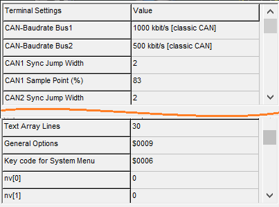
- Baudrate and bit timing parameters for the device's CAN interfaces.
Click on a value of any of the CAN-related entries to open a configuration dialog (here: dialog 'CAN Bus Parameters').
Wherever possible, set the CAN-baudrate under "Programming Tool Settings" and "Terminal Settings" to the same value - especially if you must download the application via CAN into the terminal while the application is running (which is always the case for CANopen devices ! ). If the download via CAN fails, read the extra document 'Download troubleshooting'.
- Maximum number of display pages,
maximum number of icons,
maximum number of text-array lines:
Only relevant for older devices without 'flexible storage'.
In older devices, these three parameters were required for partinioning the memory inside the terminal when downloading a new application. More on the memory distribution here.
- The keyboard combination used to enter the UPT's system menu.
Click on the value to open a dialog for the system-menu key combination (and a few other 'Options' for the UPT = User Programmable Terminal).
- Up to 32 non-volatile values which can be accessed
through the UPT's interpreter (nv[]) or via script (system.nv[]).
As for other parameters, click into one of these cells to open a special input dialog.
CAN bus timing parameters (as part of the "Terminal Settings" / "User Settings")
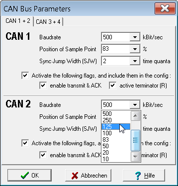
To open this dialog window, select 'Options' .. 'CAN / LIN bus settings' in the tool's main menu.
The following CAN-related parameters can be modified( * ):
- Baudrate
-
CAN-Baudrate in kBit/second. The baudrate "666" actually means 666.66666
kBit/sec; "83" is 83.33333 kBit/sec. All other (and less exotic) CAN baudrates
are precise integer values, not truncated.
- Position of Sample Point
-
Position of the sampling point within a CAN data bit. Unit is percent (of
the nominal CAN bit time). For automotive applications, usual values are
80 ... 83 percent, where 83 % is, in most cases, actually 83.3333 % . In
most devices with CANopen, this parameter has no effect.
- Sync Jump Width (SJW)
-
Width of the CAN synchronisation jump, measured in 'time quanta' units. Possible
range is 1 to 4 time quanta, but additional restrictions apply (depending
on the position of the sampling point). The CAN controller / firmware divides
each CAN bit into as many possible time quanta as possible. In some automotive
specifications, the number of time quanta per CAN data bit is also called
'BTL cycles' (BTL = bit timing logic in the CAN controller). Thus the true
SJW length (in microseconds or nanoseconds) depends on the hardware; especially
on the crystal clock frequency. As a rule of thumb, each CAN data bit is
divided into 10 to 20 time quanta. The actual value (used in the programmable
device) can be examined in the system menu, as described in the chapter titled
"CAN Bit Timing Parameters" in document #85115
(PDF) .
- Flexible Data Rate (FD)
-
Bitrate for the 'fast' data field after the CAN FD bitrate switch (between message-ID and data field).
Usual bitrates for CAN FD are 1000, 2000 or 4000 kBit/second, in rare cases also 8000 kBit/sec (if cable, connectors, and the transceivers on both sides permit).
This field is only enabled if the currently selected device supports CAN FD, for example the MKT-View V (under development in 2019, planned for 2020).
When selecting a device/display, the info about which of the CAN ports also supports CAN FD is copied from an internal database into the current device profile. For example, an i.MX RT1064 has three CAN controllers, but unfortunately only one of them supports CAN FD. In that case, the device firmware would map the FD-capable controller (called "FlexCAN3" by NXP) to the first logic CAN port ("CAN 1").
See also: Notes on CAN FD capable ports in the MKT-View V.
- Activate the following flags, and include them in the config :
-
With this (rarely used) option, during a program transfer into the target
device, settings made in the device's System Setup menu
will be overwritten with the settings from the new application (*.cvt).
If this option is not checked, the CAN-related parameters listed below
will remain unchanged (in the nonvolatile system setup, e.g. EEPROM):
- Enable Transmit and Acknowledge
-
Allows transmitting CAN frames and acknowledging received frames.
If this option is unchecked, the CAN node will be turned into a 'passive listener' (Listen-Only Mode).
Note: This option only works for devices with suitable CAN-hardware or -controller, like MKT-View III / IV / V !
- Active Terminator (Resistor)
-
Turns on the CAN bus termination resistor (usually 120 Ohms), if that resistor
is switchable aka "software controlled". Please consult the literature
on CAN bus topologies to learn where the 120 Ohm resistor should be located
(on the end of the cable or a long stub, but that's now the whole story).
Devices with a software-switchable CAN termination resistor are MKT-View II, III, IV, V, and possibly any later device. Details about the availability of a switchable terminator (and its resistance) are only in the device's datasheet.
(*) In very old devices like MKT-View "Plus", or devices with firmware older than April 2011, only the CAN baudrate could be configured, but not the position of the sampling point and the SJW parameter (Sync Jump Width).
See also:
Configuration of the PC's CAN interface (used for program transfer),
LCD settings dialog,
Optional Display Setup,
Memory distribution dialog,
UPT File Description,
System menu in the terminal ,
Table of Contents.
General Terminal Options (dialog)
(Originally only for "UPT" = user programmable terminal,
meanwhile also for MKT-View and others)
The "General Terminal Options" – dialog can be used to set some settings that will be transferred into the UPT when you upload your application. This dialog can be started by clicking on the "General Option"-value on the "Settings"-Tab.
The option Enable System Menu may be turned off if you are
shure that you do not need the UPT's system
menu functions (because you need the keyboard combination F2+F3 in your
own program and you don't want that the user of your application enters
the system menu).
However, even if the option "Enable System Menu" is turned off, you may still
enter the UPT's system menu to adjust the LCD contrast if you hold F2+F3
during power-on (but at that point, the application data are not loaded yet,
and "secret" parts of your application cannot be inspected).
The option Enable Debugging was intended to be used by the author of the UPT firmware only (because he didn't have a target debugger). You should leave this option off.
The option Readout Protection can be set to prevent reading the currently loaded application from the terminal later (via CAN or RS-232). This option is only supported by firmware compiled 2009-05-20 or later.
The option Auto-Scale for larger display resolutions should be set if your application doesn't use 'pixel-precise' graphic output, and you want to re-use a program once designed for 320 * 240 pixels on a 480*272-pixel display (without wasting space on the display). More info in the FAQs on how to migrate from the older MKT-View to the newer MKT-View II / III.
The key combination to enter the UPT's system menu can now be changed from the programming tool, because the old (fixed) combination F2+F3 collided with the application of a valued customer. Be careful with this option, because not all key combinations can be detected by some targets (especially those with multiplexed keyboard hardware). If you entered an ‚impossible‘ key combination, you can only enter the UPT's system menu by pressing F2+F3 during power-on.
See also: Supported graphic functions (dialog), LCD settings dialog, Optional Display Setup, Landscape- and Portrait Modes, Memory distribution dialog, "Settings" (tab)
Optional Setup (LCD backlight settings, formerly only accessable through the device's built-in system setup)
Since 2011-07-12, the display (LCD) in few new devices can optionally be configured through the programming tool. Formerly, these hardware specific settings could only be modified in the device's built-in system menu (via System Setup / Display Setup / LCD Dimming) .
To open the following configuration screen, select Options ... Display Setup from the programming tool's main menu .
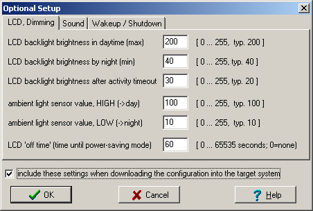
Important: When transferring the display application (*.upt or *.cvt) into the target device, these settings will only be included (in the download) if the checkmark 'Include these settings when downloading the configuration' has been set in the dialog shown above. If that option is not set, the display setup will not be saved (or sent), keeping it compatible with earlier firmware revisions.
In fact, when downloading a *.upt or *.cvt file which has the 'Include these settings'-flag set, these settings actually overwrite the system settings one single time. After that, they can still be modified through the terminal's built-in system menu, unless the key to invoke the system menu has been disabled through the 'general options'.
Note: The efficiency of certain display backlights (usually white LEDs, but sometimes CFL tubes) may vary greatly between different devices. Thus the same 'brightness' control value may give different results on different devices. Details on the automatic (ambient-light depending) LCD brightness control can be found in the description of the device's system setup menu, see document #85115 .
See also: Feature matrix (for various targets), Settings (tab), Table of Contents
Checking the supported graphic functions
Depending on your hardware- and the firmware revision, the target system ("terminal") may support one or more of these graphic functions:- Screen inversion ("inverse" means white characters on black background, see interpreter command "di").
- Graphic buttons
- Bargraph diagrams
- Y(t)-diagrams
- user-defineable fonts
- presence of a touchscreen (required for simulation)
- and other functions which were unknown at the time of this writing !
The following dialog window can be opened by clicking on the "General Option"-value on the "Settings"-Tab:
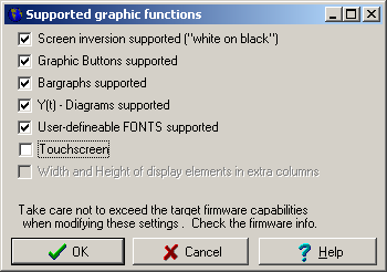
If a checkmark is not set in this dialog, it does not necessarily mean that your terminal does not support the associated function. The information which of the graphic functions are supported is embedded in the storage file (*.upt or *.cvt). If you load an "old" application, you may find some of the functions indicated as not supported, though your "new" firmware supports them. For this reason, you can modify the "support-flags" in this dialog yourself (*). Usually, after transferring the program into a terminal and reading it back (via CAN-bus) the programming tool knows which graphic functions are really supported, and sets the checkmarks in this dialog accordingly.
-
(*) be careful not to activate functions which are not supported by the firmware
in your terminal. The resulting display may look very strange after downloading
your application into the terminal !
An overview of devices, firmware variants, and their capabilities is in the feature matrix .
The option "Width and Height of display elements in extra columns" cannot be set directly. This option solely depends on the firmware compilation date. If necessary, the latter can be modified on the 'Settings' tab, for example if a bidirectional transfer between programming tool and the programmable device is impossible (i.e. transfer only via memory card). Devices with firmware older than 2009-11-27 did not support width and height of display elements in these extra columns - instead, width + height were encoded inside the parameter list of a button or bargraph (which is now deprecated).
See also: General UPT options (dialog), LCD settings dialog, Memory distribution dialog ,
Creating a UPT File Description
The 'UPT file description' is an optional text string, contained in the *.cvt or *.upt file.This description should be a short descriptive information (short enough to fit into a single line of the display). The script demo 'AppSelector.cvt' shows this string instead of the 'DOS'-filename because a DOS-filename, limited to 8.3 characters, is usually not sufficient to provide enough information (for a human operator) to pick the right application for a given purpose.
Example (from the 'AppSelector' demo, which uses a graphic table with all *.cvt files, or their descriptions, found on the memory card):
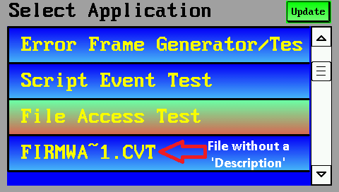
The file description can be modified by the programming tool via 'File' menu, 'Description' :
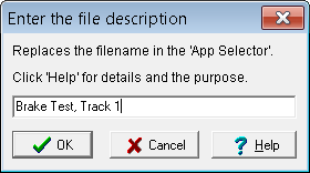
When invoking the System/Setup menu (press and hold F2 and F3), the file description is displayed in the "App-Info") field. This way, the user can check before e.g. a test drive, if the intended application has been loaded (if the application doesn't identify itself on e.g. the first programmable display page).
The script can read out this string via display.app_info.
For developers:
The file description is stored at the begin of the file, in the non-encrypted part.
That way, the 'Application Selector' script can parse it even if the file is encrypted.
The example below shows the first lines of a CVT file with the description:
; File:  c:\MKT\CANdbTerminalProgTool\programs\Brake_T1.cvt
; Saved: 2015-03-05 11:12:13
; Type:  program file for user programmable terminal
; Producer: programming tool compiled Mar  5 2015
Description="Brake Test, Track 1"
Encryption=0
PwdHint1=""
Password1=""
Simulation of the memory card (on a PC, as replacement for the memory card in a 'real' device)
To develop advanced applications (with file access via script) with no 'real' target hardware, the memory card can be emulated by a freely selectable subdirectory on the PC's harddisk (Parameter "Simulated MC" on the panel labelled "Directories").To simulate insertion or removal of the memory card (in the card slot of a 'real' device), use the programming tool's main menu, 'Options' ..
'Simulated Memory Card' (toggles between 'INSERTED' and 'REMOVED').
1.8.9 Checking for external file references (in the application)
Some display applications will access files stored on the memory card, or in certain areas of the terminal's internal FLASH memory, for example audio files.
If you wrote such an application, and need to pass it on to somebody else (a customer, colleague, etc), don't forget to include all files which your application uses.
To simplify this task, the programming tool checks for external file accesses during the simulation, and when 'checking all pages'. The result of those tests can be checked by selecting "View".. "External File References" in the programming tool's main menu ("Ansicht".."Externe Datei-Referenzen" in German) :
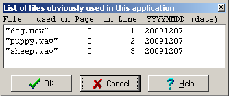
Each line of the file list contains the name of a referenced file, the display page on which the file was referenced (if it was referenced on a display page), the line number, and the date in ISO-8601 format when the file was last referenced (this hasn't got anything to do with the file's creation date).
If you are sure you don't need the file list anymore, you can delete the entire list in the dialog shown above by clicking the 'Delete' button (button with a red cross symbol).
If you think that certain files are missing in the list, or some old files shall be removed from the list, you can do this manually by editing your UPT (or CVT) application with a text editor. You can find the list of referenced files in the section 'Audio- and other files (REFERENCES)', for example:
-
; ----- Audio- and other files (REFERENCES) -----

      a file0="dog.wav"   pn=0 li=1 da=20091207

      a file1="puppy.wav" pn=0 li=2 da=20091207

a file2="sheep.wav" pn=0 li=3 da=20091207 - where
-
pn= page number,li= 'line of page', andda= date in ISO format.
The length of the file reference list is limited to 64 entries (due to memory restrictions in the terminal firmware).
Finding all references to external files may sound trivial, but it's not. Consider this interpreter command :
-
audio.play( "msg" + str("***",AudioMsgNumber) + ".wav" )
where 'AudioMsgNumber' is a numeric value received through some communication channel. It is impossible (at least for the programming tool) to find out which audio file names will actually be produced by the above string expression. Even during a simulator session, not all possible values of 'AudioMsgNumber' may occurr. So, if your application uses tricks like the one shown above, maintain a list of all files used by your application, and don't forget to distribute (or upload) them along with your *.upt or *.cvt file(s).
User-defined fonts may be considered 'external files' too, but at the
moment, they are not (and thus *.fnt files are not listed in the file reference
table). To find out which user defined fonts are used, check the
user-defined font list.
Definition of a Text Array
The Text Array is used to define an array of single text lines that you may use in your application to display "text messages" depending on a numerical value.To use a text array, you have to define how much memory shall be used for text lines. You must sacrifice some "display pages" to get more "text lines". See the settings tab for more info.
To read lines from the text-array in your application, you may call some string functions in text display commands.
You can find a simple example for text arrays in the second demo file.
- Hint:
- If you only want to display two or three text alternatives (like "ok"-"too hot" - "too cold"), depending on a numerical value, you can use the interpreter's "arithmetic if-then-else" within a format string. This is explained in the chapter BUTTONS(!).
See also:
- Popup window (can be used to show text messages which are received from the CAN-bus; acts like a small virtual terminal inside the terminal).
- String functions
- Array in the script language (an alternative to the display interpreter's single 'text array', but the script language is not available for some older devices)
Back to top
Display Page Definitions
A UPT 'display application' contains one or more 'display pages'.The Page Definition tab is used to define a single display page for the terminal.
It is grouped into several tab which are explained in the following chapters.
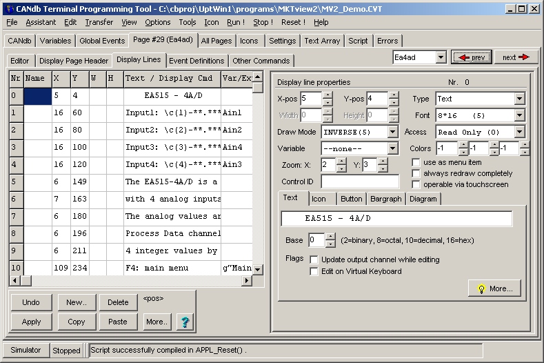
(Screenshot of the 'display page definition table' in the programming tool)
Introduction to Display Page Definitions
A display page consists of :- a header definition
-
multiple display elements which can be defined in text form,
or with the 'graphic' editor.
Examples:- simple Text, with or without the value of a variable (using placeholders like '*****.*'),
- advanced text displays, using backslash sequences,
- edit fields,
- multi-line menus,
- icons (graphic images, switchable depending on signal values),
- bargraphs, vertical or horizontal,
- buttons (user-defineable touchscreen areas),
- Y(t)- and X/Y-diagrams,
- text panels (can be 'printed to' via script),
- graphic panels (displays a tCanvas, filled via script),
- tables (via script, also useable as control element / selection list / etc),
- analog meters (pointer instruments),
- lines, polylines, closed and filled polygons,
- ...
- some rarely used low-level graphic display commands
- event-definitions (explained later in this manual, after the introduction of the interpreter language. Only required for special applications ! )
Besides the page definition table shown above, display pages can also be modified with a graphical editor (more on that later) :
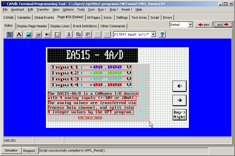
(Screenshot of the 'simple graphical editor' for programmable display pages)
After starting, the programming tool shows 'page zero' of your application (like the 'real' display after power-on).
To switch to an other page of your terminal program, you may use the
page overview , where you can see all pages
that you have already programmed.
To switch from one display page to another in the programming tool,
use the red-arrow-buttons
(![]() ,
,![]() in the upper right corner) or the
display page overwiew, where you can see all
programmed pages.
To switch to another page in the terminal, use
buttons, menus,
self-defined events, script,
or page-scan-sequences . But first, let's look at
the elements which belong to a single display page...
in the upper right corner) or the
display page overwiew, where you can see all
programmed pages.
To switch to another page in the terminal, use
buttons, menus,
self-defined events, script,
or page-scan-sequences . But first, let's look at
the elements which belong to a single display page...
Page Definition Header
The Page Definition Header contains general information about a display page, like :
-
the NAME of the page. Please replace the automatically generated
name by something more descriptive, like
"MainMenu" instead of "page2". For most target systems, up to 8 characters are allowed (no spaces) - the flag "Always redraw this page completely"
- the flag "do not clear the screen automatically"
(Leave this option unchecked unless you really need it. When set, the system will not automatically clear the screen before rendering the elements on the current display page. In this case, it's your responsibility to clear the screen 'programmatically', e.g. controlled via script or display-interpreter command). - the flag "do not update the screen if keyboard buffer is full"
- the flag "circular wrap when navigating"
- the flag "inverse screen (dark background)" [only for certain terminals]
- the flag "include this page in the page-scan sequence"
- A page update interval (in milliseconds), which can reduce the page-update rate, to improve readability of numeric values which are otherwise updated too frequently (making it difficult to read the numbers, especially on stoneage passive LCDs).
- Default text colour, default background colour, Day/Night: Only for colour displays. Details and an example are in another document.
- Special Background Filler: Usually, the background of a display page is just a "blank screen". If you enter one of the graphic commands in this field, it will replace the automatic "Clear Screen" operation. Beware: The "background filler" should erase the entire screen, not just a part of it. Example: Command to fill the screen (here: background) with a colour gradient.
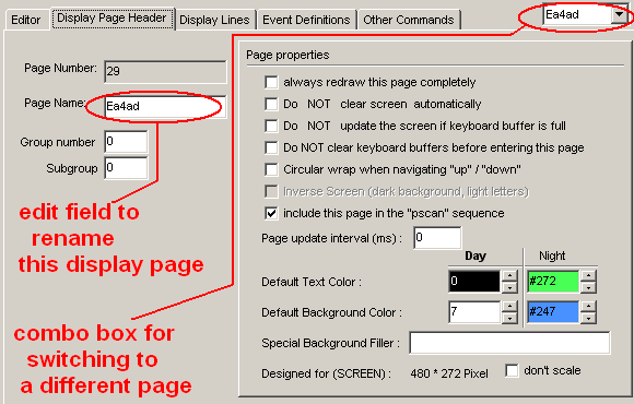
(Screenshot 'Display Page Header' for a programmable page)
If the option always redraw this page completely is selected,
the whole page will always be updated completely. This requires quite a lot
of CPU time but may be necessary if you use
overlapping or moving graphics. A complete
screen update always includes erasing the screen, so there will be no remaining
garbage on the display if you let an icon crawl across the screen.
If "always redraw.." is not activated, only the text lines with modified
contents may be updated to save some CPU time. A typical display update-rate
will be about 10 screens per seconds (but this depends very much on the number
of display-lines with flexible contents).
A typical display-update with the option "always redraw.." took about 250 ms
(on old terminals like "UPT-515" and "MKT-View" / "MKT-View Plus" with 8- or 16-bit CPU).
On newer devices with Cortex-M CPU (like MKT-View III), even a complete screen-update
usually takes less (much less) than 100 milliseconds.
In any case, the update rate greatly depends on the complexity of the display page,
and the screen resolution.
As an alternative to the option always update page, you can
use the option always update this line on the display line property
panel. This will save a lot of CPU power, especially if a large display or
a color display is used (UPT 167, IPE-VIEW, MKT-View I / II / III).
Definition of Display Lines
To insert new display elements the easy way, right-click into the simulated LCD, and select what you want to insert from a list. The programming tool adds a new display-definition-line to the table which is described below. Alternatively, you can use the "simple page editor" which is explained in another chapter. Expert users will perfer to type (or copy) the definitions into this table manually.All definitions for display lines are shown in a table on the page definition sheet:
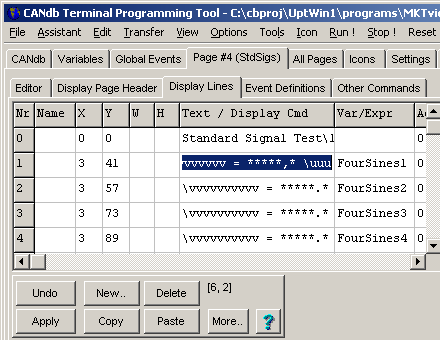
Cells highlighted with a red background indicate errors detected during the last invocation of 'Check & correct all display pages' (in the main menu under 'Assistant'), e.g. using an undefined variable (a 'display variable' that no longer exists, or doesn't exist because the display page has been copied and pasted from another application).
The buttons below the table are used to modify the table's contents. INSERT, DELETE, COPY and PASTE operate on complete lines. The MORE-Button opens a popup menu (which you can also open by clicking into the table with the right mouse button).
- The columns (or edit fields) labelled "X" and "Y"
-
define the position of the upper left corner of the element defined in this
line, measured in graphic pixels.
Besides entering the pixel coordinate in numeric form, you can use the graphic editor to modify an element's position.
-
The columns "W" and "H" -
define the width and height of certain (not all!) display elements, measured
in pixels. For 'normal' alphanumeric display lines, these fields may be
empty (unless text shall be centered or aligned in a fixed-size field).
For other 'fixed size' elements (like buttons, etc) the size must always be specified.
For devices with firmware older than 2009-11-27 (ISO, YYYY-MM-DD), the columns "W" and "H" are not displayed in the table, because old devices (MK-View 1) / old firmware do not support these properties. In case of doubt, check your device'sfirmware compilation datein the system menu, and -if necessary- let the programming tool know the compilation date of the device firmware on the 'Settings' tab under 'Firmware compilation date'.
For "normal text fields", width and height are usually not specified (so the element only occupies as much space on the screen as it needs to). For aligned text fields, the field size must be specified (for right-aligned text, at least the width).
In the graphic editor, the size can easily be modified by pulling the lower right 'sizing corner' (small square) with the mouse.
- The "Name" column
-
is rarely used so far (because only terminals with 32-bit CPU support this
function). If a display element has a name, you can easily access it from
the interpreter or via script, using this name as a reference.
The maximum length of any name in this column is 7 characters.
More details here .
- The "Text" column
-
can be used as format string for numerical values,
or as a menu item. The text string can also
be used to display icons ,
bargraphs, buttons and
other special graphic elements.
- The column "Var/Expr" column
-
usually contains the name of a variable, a numeric
function, or a string function which shall be
displayed/edited or an interpreter command which shall be executed if a menu
entry has been activated. The calculated value can be accessed from the
interpreter with the "v"-function.
- The "Access/HotKey" column
-
defines the access rights for a displayed variable or a ‚hotkey‘
definition if the display line is used as a menu item (more about this on
the property panel).
- The columns "Draw Mode", "Color", "Font" etc
-
affect the appearence of the displayed line on the screen (see property panel).
The "property"-panel on the right shows more detailed information about one single display line.
You may edit the properties of a display line in the table or on the property
panel, the information will always be updated on both parts.
To inspect the current value
of variables or expressions in the page definition table,
simply point the mouse over the cell (without clicking). If the interpreter
can evaluate the 'word', sub-expression, or the complete expression under
the mouse pointer (details here),
the result will be displayed in the rightmost field of the status bar
at the bottom of the main window.
If the simulated LCD is visible, you will
immediately see the effects of the changes to a display line. For example,
if you change the Y-Position of a display string via up/down-scroller in
the display line property panel, you will see the text moving on the simulated
LCD screen. The currently edited display line is marked with a dotted rectangle.
If some graphic elements or text lines on the screen overlap, you should be aware of their drawing order ! The order of the definition lines can be modified with the mouse. Hold the left button pressed while moving the mouse in the column "Nr" up or down. A black horizontal bar shows the location where the moved entry will be inserted when the mouse button is released. This row-moving procedure is also possible in some other tables of the programming tool.
Many possibilities are explained in the UPT examples
(separate document in HTML format, some examples for the MKT-View terminals
can be found on the MKT website).
Display Line Properties
The "display line property" panel shows the properties of a single display line that you selected in the display line table.
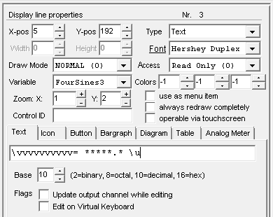
Display Line Properties are:
- X-position, Y-position
- Width and Height of the display element. Details here.
-
Draw Mode (i.e. normal, inverse, blinking; only for monochrome displays).
For colour displays, this field is meaningless because they don't support "blinking" text.
-
Text- and background- colours (only for color
displays).
For displays with 256 colours or more, you can double-click these fields to select a colour from a palette.
The second background colour is used for gradient fills in graphic buttons and similar objects, and to fill polygons.
Standard colour values are listed here.
Hint: Set both foreground- and background colour to -1 (minus one) for most display lines. The terminal will use the default values (from the page header) in that case, so you can easily switch between day- and night-design as explained here. -
Font (since 2018, the drop-down list also contains a few vector fonts).
- 1 : Fixed bitmap font with 4*6 pixels
- 2 : Fixed bitmap font with 6*8 pixels
- 3 : Fixed bitmap font with 7*12 pixels
- 4 : Fixed bitmap font with 8*8 pixels
- 5 : Fixed bitmap font with 8*16 pixels
- 6 : Fixed bitmap font with 16*16 pixels
- 7 : Fixed bitmap font with 16*32 pixels
- 8 : Fixed bitmap font with 32*32 pixels (only for devices with 'large' displays)
- 9 : Fixed bitmap font with 12*24 pixels (only for devices with 'large' displays)
- 10 .. 15 : User-defined bitmap fonts
- 21: Vector font 'Hershey Simplex' (freely scalable, with thin lines)
- 22: Vector font 'Hershey Duplex' (freely scalable, with double lines)
- 2 : Fixed bitmap font with 6*8 pixels
To find out which of the fonts are really supported by a certain device, switch to the programming tool's 'Settings' tab, Terminal constants, scroll down to 'supported fonts', and double-click on the hexadecimal value. Each bit represents one of the font numbers listed above.
- 1 : Fixed bitmap font with 4*6 pixels
-
Zooming factor for text and bitmaps. There are individual controls for
'X' and 'Y' (horizontal and vertical axis).
Bitmaps and bitmap-fonts can only be zoomed by 1,2,3,4 .. 15 (integer factors). The scaling range for vector fonts is 0.2 to 15.9, because vector fonts can not only be magnified, but also downsized in small steps.
-
Variable/Expression/Menu Command
For any kind of 'display element', this field contains the name of a display variable (which delivers the displayed 'value'), or a short numeric expression, etc.
If the display element is used as a menu item, this field may contain an interpreter command which is invoked when the user selects the item.
-
Access: The value of
a variable with READ/WRITE access can be
edited during run-time (integer
values only, no floats).
If the access is "read only", the value can be displayed but not modified on this page.
Certain display elements (like bargraphs) will turn into an interactive control element, if this field (in the 'display line properties'!) is set to read/write instead of the default 'read only' access. For example, a bargraph can be used as a slider or scrollbar, operated via touchscreen. -
Control ID: Only required
when events for this control element (button, menu item, edit field) shall
be handled in the script
language.
The control ID allows to identify which control element has fired the event, by using a select...case statement in the script.
If this field is empty, the script will not be notified if "something special" (-> event type) happens with this control element.
If a script with user-defined constants already exists (and was successfully compiled), the control ID can be picked from a list by double-clicking the 'Control ID' field shown above: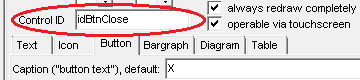
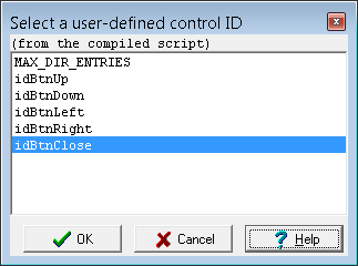
Screenshot with a list of user-defined script contstants,
after double-clicking on 'Control ID' in the programming tool. -
"This line is a menu item"
Setting this flag turns a simple Display Line into a menu item. The user may move through the menu on a display page using the cursor keys and press ENTER to execute the command defined in the property "Variable/Expression/Menu Command" . -
"always redraw this line
completely"
forces the UPT to repaint a single line of the display as often as possible. Use this option if a line has "side effects" like a dynamic text display. You do not need this option to display a simple variable which may change its value (the UPT firmware takes care of this). - "Text" (title of an extra tabsheet in the panel's lower part):
- Text (input): Static text and/or a format string with optional
backslash sequences)
- Flags :
- "Update output channel while editing"
- With this flag set, the current value of an edit field will be transferred to the output channel while editing the field, not only when pressing ENTER to finish editing.
- "Edit on Virtual Keyboard"
- If the value is editable, and the operator wants to edit it, open the Virtual Keyboard to edit the value there.
- Base : Show value in binary, decimal, hexadecimal form, or from a value table ?
0 = "automatic" : If possible, show string from the variable's value table.
If that's impossible (no matching entry in the value table), show it in decimal form.
2 = Show the value as a binary number (base two)
10 = Always show the value as a decimal number (base ten); no value-table lookup
16 = Show the value as a hexadecimal number
In any case, the number of placeholders (*,#) in the format string specifies the number of digits, or limits the number of characters displayed from a value table.
- Text (input): Static text and/or a format string with optional
backslash sequences)
Properties wich are not supported by a particular device will be disabled on the panel (weak gray color).
The connection between display lines and variables can be easily modified
with the Variable Selection Dialog.
Format String (for display lines)
A "format string" is one of the display line properties of a display line definition. It may contain the displayed text itself, or define how the contents of a variable shall be formatted for the display (thus the name).The format string can...
- be a simple constant text string like "Hello, world !"
- be a 'switch-list' of different strings, to be selected from a numerical value
- contain special "place holders" like "****" for numeric digits or variable strings
- contain several backslash sequences as explained below
- be used to display icons (in backslash sequences like "\iMyIcon" )
- contain a few simple HTML-like tags, e.g. '<u> underlined text </u>'
- also be used to control the behaviour of edit fields.
Special characters in a format string, backslash sequences
(Note: the following list only applies to 'modern' devices with 32-bit CPU. Older devices like "MKT-View" (with 16-bit CPU) and "UPT-515" (with 8-bit CPU) only support a small subset of the features listed below.)-
* (asterisk) will be replaced by a numerical digit or a single character from a string - For floating-point values, leading zeroes are suppressed (replaced by spaces), but not for integer values.
-
# will be replaced by a numerical digit, similar as the asterisk (*) . - In contrast to the asterisk, leading zeroes are ALWAYS suppressed (for integer as well as floating point).
-
0 (digit zero): will be replaced by a numeric digit from the value (like '*' and '#'). - In contrast to '*' and '#', zeroes are NEVER suppressed by this placeholder.
-
. (point) is the decimal separator. - CAUTION: Older devices didn't support floating-point values in an edit field !
-
, (comma in the Format-String, not in interpreter commands) -
can be used as decimal separator for german users since 2009-10-06;
but only if the comma is immediately followed by a placeholder for a digit. -
- will be replaced with the sign - of a numeric value (+,-)
-
\\ displays a single backslash
\< displays an opening angle bracket (instead of interpreting it as an HTML tag)
\- displays a "-"-character (minus character, not a placeholder for the number's sign)
\0 displays a "0"-character (zero character, not a placeholder for a digit) -
-
\ar align right (applies to the rest of the text string within its field (*) )
\al align left (applies to the rest of the text string, up to the next alignment option (**))
\ac align centered (applies to both X and Y, for the rest of the string, within its field (*) )
\ah align horizontally centered (center the X- but not the Y-coordinate, i.e. center only horizontally, and leave the vertical position unchanged (*) )
\av align vertically centered (aligns the rest of the string vertically; horizontal position remains unchanged (*) )
\at, \ab : Reserved to align fields on the screen (not the text within its field)
-
Only for targets with 32-bit CPU and firmware compiled 2013-03-25 or later.
The right and bottom margins for output is the position ("X","Y") plus the fixed size of the display element.
Without a fixed size of the display element, most of the 'alignment' switches treat the right and lower edge of the screen as 'the end' of the alignment area.
The following example from programs\AlignTst.cvt uses coloured backgrounds to show the alignment areas:
(**) Because left-aligned text is the default, the alignment option '\al' (align left) is hardly ever used.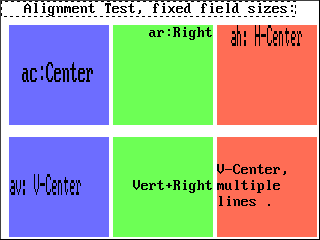
\acac:Center \arar:Right \ahah: H-Center \avav: V-Center \av\arVert+Right \avV-Center,\nmultiple\nlines .
It was implemented to modify the default center aligned text on graphic buttons.
-
\bar(width,height,flags,ticks,pattern...) -
inserts a Bargraph (only supported by certain
devices, explained in another file)
-
\btn(width,height, ...) -
draws a Button (only supported by certain
devices!)
- \chr(N) displays a single character with the code N, from the currently selected font. Examples:
-
\chr(65) displays the letter A.
\chr(v) displays a character with the code resulting from the numeric expression in the current display line (see "v"-function)
\chr(56) displays a "fast forward" symbol, if the user-defined font font "Webd3232" is selected (only for certain terminals). "Webd3232" is a symbol font, compatible to "Webdings" (c) Microsoft Corporation.
Since 08/2016, for devices like MKT-View III,IV, chr(N) also supports a few Unicode symbols. For Unicode, the code (N) should be expressed as a four-digit hexadecimal number (prefix 0x), e.g.: \chr(0x2611)
(draws a 'checkmark in a box', ☑, usable for 'checklist' tables and buttons with a checkmark).
Alternatively, use backlash-U to show characters by their hexadecimal Unicode value.
- \cN sets the text- (and "foreground"-) colour for the subsequent output.
- N should be one of the standard colours defined here.
Example: \c7 sets the text colour to white.
- \CN sets the background-color for the subsequent output.
- Also here, N should be one of the standard colours defined here.
Usually, there's no need to change the colour within the format. Instead, text colours are defined by the display line properties.
Example: \C0 ("Colour Zero") sets the background colour to black.
- \dia( <diagram-definition> )
- part of a Diagram-definition (only supported by certain devices!)
- \e( <expression> )
- Evaluate a string expression (instead of
a fixed string). Only allowed at the begin of the format string in a display
line definition.
- \fN (N=font number as used in the display line panel)
- selects font number N for output.
Example: \f
- \fr(x1,y1, x2,y2)
- draws a rectangular frame. The coordinates are *relative* to the display
line's position. Example: Menu \M0\fr(-2,-2,260,32)
- \fi(x1,y1, x2,y2)
- Draws a solid ("filled") rectangle with the current foreground colour.
Also here, the coordinates are relative to the element's position.
- \i<Icon-Name>[,<Invert-Flag>]
- inserts an Icon (see examples below). This sequence is usually generated
by the programming tool (automatically, when placing an icon on a display page),
but it can also be generated at runtime via script, e.g. to display
glyphs for far-east languages in a table-driven translation
('internationalisation'). Example:
\i"hourglas"(here with the name limited to 8 characters, to eventually load the image from a file at runtime, on a FAT file system without 'Long Filenames').
- \li( [options] x1,y1, x2,y2 [, x3,y3, ..] )
- draws a graphic line or a polygon. The coordinates are *relative* to the
display line's position. Options: w=width(1..3), p=pattern (16-bit for 16
pixels).
A comma between two points (coordinates) draws a line between these points, a semicolon does not (it only 'moves the pen' to the new point without drawing, aka 'pen up').
As for most other display elements, the colours used for lines or filled polygons are taken from the display element's drawing colours :
- Solid lines are painted with the foreground colour
(the same colour as used for normal text, inidividually defined for each 'definition line'); - The background of the polygon's rectangular drawing area may be filled with the first background colour,
or left transparent (dummy colour value "-2" = transparent). - Filled polygon areas ("polyfill") use the second background colour.
To insert or edit polygons, the graphic editor can be used instead of editing the polygon 'as text'. But variable coordinates (etc) for animated graphics are only possible by entering the '\li' sequence manually. Examples of the \li sequence with open, closed, and filled polygons -some of them quite tricky- can be found here.\li(0,15, 100,15) draws a line between the two coordinates (relative to the object's position) \li(w=2,polyfill(13,44,52,44,32,12)) draws a filled triangle with 2-pixel wide border \li(font=1, "Test" ) draws a few characters using font 'Hershey Simplex' \li(font=2, rot=45, "Test" ) draws text rotated by 45° (positive = clockwise)
\mN switches the draw mode- for the following displayed characters in the current line. In a selected menu line (inverted), the mode is inverted automatically. The mode may be a numeric expression in parentheses.
Example: "\m((v>0?0:10)" sets the draw mode to 'normal' (0) if v is greater than 0, and to 'erase'(10) otherwise. This allows you to hide certain parts of the display depending on variable values.
The draw mode values are the same as for the interpreter commanddm.
\MN switches the draw mode- for the following displayed characters in the current line. Unlike "\m", the mode will not be modified even if the display line if "inverted" as a menu selection.
\n new line (plus carriage return).- The output position of the following text is moved to the left margin (=position defined in a display line) and the next line.
\panel [(optional options)] : multi-line text panel.- Defines a rectangular area, which can be used by the script language to display lines of text (like a small text display window).
At the moment, the multi-line text panel can only be filled by the script language, using the print command. Details about the 'panel' element are here .
\s(<condition>)?"<string1>":"<string2>" (available since May 2003)- A "switch"-list for strings. Depending on <condition> (a comparison, etc), either <string1> or <string2> will be displayed. Follow the link for details.
\script.<function name>(<argument list>)" (only for devices with script language)- Invokes a script function to retrieve a text string. The result value (which must be a string) is inserted instead of the backslash sequence. Follow the link for details.
\vvv- placeholder for the name of a VARIABLE. The backslash itself is part of the placeholder, so "\vvv" will show only the four first letters of the variable's name.
Prefixes like "script." will be skipped (not displayed on the screen).
\uuu- placeholder for the UNIT of a variable. The backslash itself is part of the placeholder, so "\uuu" will show four letters of the unit. If the unit is shorter (like °C ), the rest is filled with spaces.
- \U+<hexadecimal Unicode>
- Draws a single Unicode character by its hexadecimal code (only one "code" per backslash-U).
Example (in a format string): "\U+1F50D Zoom in" .
The hexadecimal code ends with the first non-hex character (usually a space as in the example, which draws a "left-pointing magnifying glass" if that character exists in the current font).
Supported special Unicode characters (and in which fonts they can be rendered) are listed here.
Most Unicode-'special characters' (with codes above 0x00FF) are implemented in the vector font 'Hershey Simplex'.
\x hexadecimal coded special characters (plural, since October 2009)- Begins a hexadecimal code sequence of 8-bit characters, similar to the "C" programming language. All characters after Backslash-x are interpreted as two-digit hexadecimal character codes. For each code, the equivalent character is emitted using the current font. Details about backslash-x (and how to generate such sequences) are here.
\zN- sets the zoom factor for characters. ONLY FOR DISPLAYS WITH 16-bit CPU. "\z0" restores the programmed default zoom for the current display line. To set the horizontal and vertical magnification factor independently, use two digits like this:
\z14High but Narrow \z0Back to normal - Solid lines are painted with the foreground colour
\s(<condition>)?"<string1>":"<string2>" Conditional sub-strings (available since May 2003)
A "switch"-list for strings. Depending on <condition> (a comparison,
etc), either <string1> or <string2> will be displayed.
<String1> is used if <condition> is non-zero (= TRUE), otherwise
<string2> (the 'else'-branch).
The condition should use the numeric function 'v' to access the value of the variable
is displayed in the current line.
The comparisons can be nested, if more than two possible strings shall be displayed.
Examples:
\s(v<15)?"too cold":(v>25)?"too warm":"Temp ok"- If 'v' (Value of the variable) is less than 15, the display shows 'too cold'.
If 'v' is greater than 25, it shows 'too warm'.
Otherwise, it shows 'Temp ok'.
\s(v)1"Mon":2"Tue":3"Wed":4"Thu":5"Fri":6"Sat":7"Sun":"err"- Here, the value of <v> is compared with the constants 1, 2, 3,...7,
until a match is found. If there is no match, the string "err" is displayed
in this example. As an exception, the questionmark (used as "if"-suffix)
is not manatory here.
\s(v)0"Zero":1"One ":2"Two ":"****"- Values 0, 1, 2 are shown as plain text,
all other values are shown in numeric form (decimal, integer, four digits).
func OneTwoThree( int n )
   select n
      case 0 : return "Zero";
      case 1 : return "One";
      case 2 : return "Two";
      case 3 : return "Three";
      else   : return itoa( n, 4 );
   endselect;
endfunc;
Under 'Display Lines', column 'Variable / Expression', the following expression would be entered instead of the variable. In this example, the value of 'X' (Variable) is be passed to the user-defined script function 'OneTwoThree', which then returns a string, which finally replaces the asterisks in the format-string:
script.OneTwoThree( X )
Hex-coded special character sequences
Backslash-x begins a hexadecimal code sequence, similar to the "C" programming
language. All characters after Backslash-x are interpreted as two-digit
hexadecimal character codes. For each code, the equivalent character
is emitted using the current font.
This function is especially suited to display special characters, for which
there is no equivalent "key" on a western PC keyboard.
The hexadecimal numbering scheme makes this quite easy to achieve:
If the (up to 256) characters of any 8-bit font are displayed (or printed)
as a grid with 16 * 16 fields,
-
with the 16 grid columns labelled 0..9,a..f;
-
and the 16 grid rows labelled 0..9,A..F;
then the first (most significant) digit of the hexadecimal code is the table
row (0..9,A..F); while the second (least significant) digit is the table
column (0..9,a..f).
For the terminal, it doesn't matter if A..F or a..f is used in a hex number.
We only use A..F in the most significant digits, and a..f in the least
significant digits to improve the readability of "longer" hex sequences.
In contrast to the "C" language, the hex sequence may be as longer than just
one character. It ends at the first letter which is not a valid hex digit
(for example, the space character).
The following example will show 'Hello ' if a normal alphanumeric
ASCII font is used:
\x48656c6c6f .
To create a hexadecimal sequence of 'special characters', click on the 'more'
button of the text line definition panel, and select Font
Table.
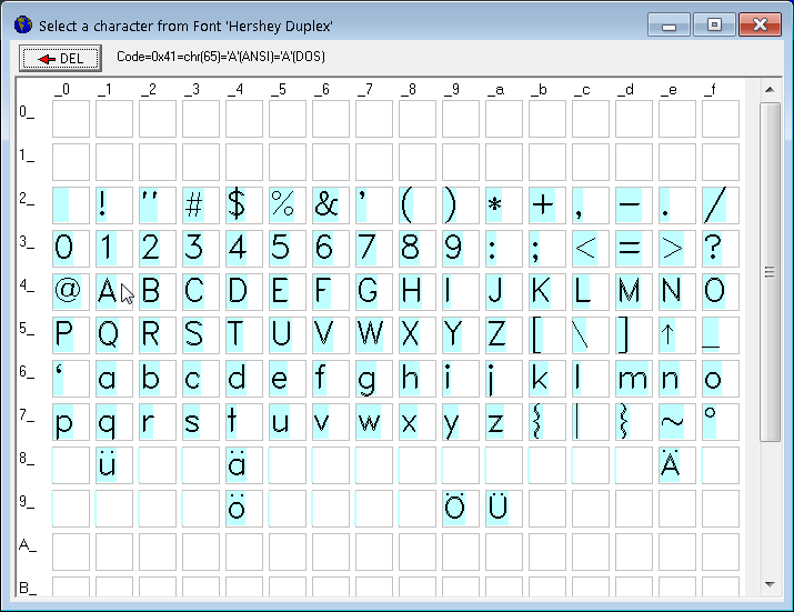
(click into the font matrix to append a character to the backslash-x sequence)
Hex values above 0x00FF (= decimal 255) are treated as Unicode characters
by the LCD driver. But from the large amount of 137000 known
'Unicode characters',
only a small subset can be rendered. At the time of this writing (2018-12), the following
characters could be rendered from the 'Hershey Simplex' font.
To embed such codes in a string, use backslash-U (for "Unicode"), not backslash-x.
           U+0203C = Unicode Character 'DOUBLE EXCLAMATION MARK'
           U+02190 = Unicode Character 'LEFTWARDS ARROW'
           U+02191 = Unicode Character 'UPWARDS ARROW'
           U+02192 = Unicode Character 'RIGHTWARDS ARROW'
           U+02193 = Unicode Character 'DOWNARDS ARROW'
           U+02194 = Unicode Character 'LEFT RIGHT ARROW'
           U+02195 = Unicode Character 'UP DOWN ARROW'
           U+025AD = Unicode Character 'WHITE RECTANGLE'
           U+025B3 = Unicode Character 'WHITE UP-POINTING TRIANGLE'
           U+025B7 = Unicode Character 'WHITE RIGHT-POINTING TRIANGLE'
           U+025BD = Unicode Character 'WHITE DOWN-POINTING TRIANGLE'
           U+025C1 = Unicode Character 'WHITE LEFT-POINTING TRIANGLE'
           U+02610 = Unicode Character 'BALLOT BOX' (empty "checkbox")
           U+02611 = Unicode Character 'BALLOT BOX WITH CHECK' (checkmarked)
           U+02612 = Unicode Character 'BALLOT BOX WITH X'
           U+1F50D = Unicode Character 'LEFT-POINTING MAGNIFYING GLASS'
           U+1F50E = Unicode Character 'RIGHT-POINTING MAGNIFYING GLASS'
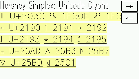
See also: Unicode via function 'chr()', User-defined fonts,
Displaying special characters in a table (via Unicode),
Example: Buttons with a checkmark (via Unicode).
HTML-like 'tags' in the format string
Devices with firmware since 2017 support a few HTML-like 'tags' in the format string. For users familar with HTML, they may be easier to use than the backslash sequences listed in the previous chapter. At the time of this writing (2018-07-25), the following tags were supported:- <b> bold text </b> (only looks good with vector fonts or large bitmap fonts, at least 12*24 pixels)
- <i> italic text </i> (artificial 'italification' by skewed printing, only ok for vector- or large bitmap fonts)
- <u> underlined text </u>
- <wN>text rendered with N-pixel wide lines</w> (only works with vector fonts)
In contrast to real HTML, the display interpreter isn't picky about nesting, and it doesn't care if beginning and ending tags are perfectly balanced. The following is ok for the display interpreter, but it would be illegal in HTML:
This text <b>is bold, <u>now also underlined,</b> now not bold anymore, </u> now not underlined anymore.
Samples with a few built-in fonts 'made bold and/or italic' can be seen in programs/FontDemo.cvt .
Edit Fields on a programmed display page
By granting 'WRITE'- or 'READ/WRITE' access to the associated variable in the definition of a display element, the element can not only show the value of the associated variable, but also modify it.Same as for normal numeric or alphanumeric display fields, the appearance is controlled via format string (* = placeholder for a digit or character, etc).
Example from applikation programs/EditTest.cvt:
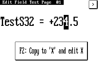
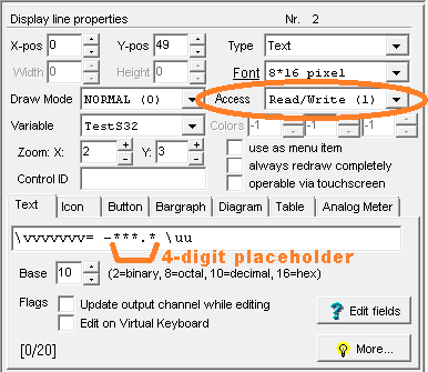
Notes on edit fields:
- The edited variable must have read+write access, both in the variable-definition table and in the display definition.
- The variable must be an integer, floating point, or 'string'
- In old devices (e.g. MKT-View I aka "MKT-View Plus"), only variables with data type 'integer' could be edited.
- Even if an edited variable is 'only' an integer, you can insert a decimal separator ('.', point !) in the format string to make it look like a fixed point value. For example, if you have an editable temperature value ranging from -20.0°C ... +70.0°C coded as -200 ... 700 in an integer variable, use a format string like "+**.*" (one decimal place after the point). If the display is in edit mode, the user can only select the three decimal places with the cursor but not the decimal point.
- Variables which receive their values from CANdb Signals (in the MKT-View terminals) cannot be edited.
- To enter edit mode for a certain cell, and to navigate between edit fields on a display page, use either the cursor UP/DOWN key or the rotary knob.
- For special applications, you can check if a field is in select- or edit-mode with an interpreter function (mm).
-
If an edit field isn't connected to a display variable, but -for example-
to a global script variable, the display interpreter doesn't know your variable's
limiting range (min,max) when incrementing or decrementing the value via cursor keys
or rotary encoder.
To set a custom min/max range when 'beginning to edit' in such cases, you can
define a Control Event Handler (OnControlEvent /
evBeginEdit )
in your script, which writes
the min / max range for editing into the system variables display.EditValueMin
and display.EditValueMax .
By listening for the evEndEdit event, a script can check and 'apply' the modified value after the operator finished editing it.
This may appear a little clumsy on first sight, but it allows those min/max ranges to be determined at runtime, read from a database, received via CAN, etc.
Buttons (on a programmable display page)
Buttons are graphic areas (on the display screen), which, when operated, can invoke a freely programmable action.The following methods can be used to operate a button :
- Pressing the optional hotkey (assigned to a certain button)
- Select the button with the cursor keys, or the rotary encoder knob, then press ENTER
- Use the touchscreen (optional, only available for certain devices)
Depending on the display hardware (TFT, colour or monochrome..), buttons can have different colours, colour gradients, or styles. For TFT displays with at least 255 colours, buttons can be transparent (or completely invisible), so they can be placed as invisible 'active touchscreen areas' over a background image (bitmap).
Details about the programmable buttons can be found in
this extra document .
Icons (bitmap graphics on a display page)
Icons can be inserted on a display page as a single graphic element (on the tabsheet 'Page #X' .. Display Lines, using the 'New' button near the lower left corner of the main window; or with the 'icon' tool in the simple page editor).Internally, an icon is just another backslash sequence in the format string for the display editor. The general syntax is:
\i<Icon-Name>Example (code automatically generated by the page editor):
\i"Earth2"displays an icon named "Earth2" at the element's graphic position (specified on the display line properties tab).
Usually, all icons must be imported into the display application before they can be used (exceptions further below).
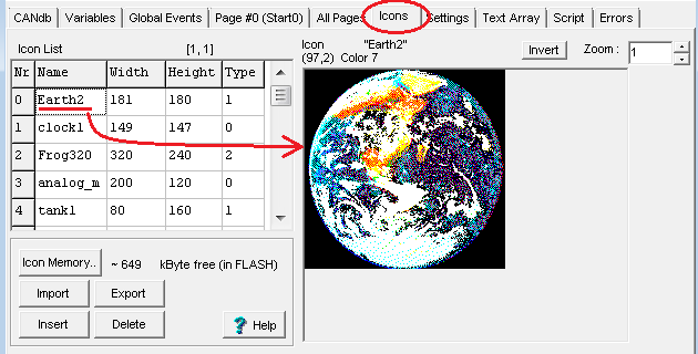
(screenshot of the 'icon import' tab)
It is also possible to use different glyhs for an icon, depending on the current value of a variable or expression, or (for monochrome bitmaps) to invert their foreground- and background colour depending on the state of a variable or numeric expression. Example (on the "properties" panel):
![]()
(screenshot of a complex icon definition on the "properties" panel)
- If the Icon in a "\i<Icon-Name>"-sequence is unknown (because it is not defined on the Icon Page), the sequence will be displayed as normal text.
-
You should activate the option "always redraw this line" in the line property
panel header, if you use "invertable" icons in a display line.
Reason: The interpreter may not notice that the state of the <Invert-Flag> has changed because the Invert-Flags are evaluated only if a display line is "redrawn".
To use the value from the "var/expr"-field as invert-flag, use the "v"-function. -
You should activate the option "always redraw this page completely" in the
page definition header, if you use the "\m<Draw-Mode>"-sequence in
a format string and <DrawMode> is a variable expression.
Reason: Same as above.
- In devices with 32-Bit-CPU (like MKT-View II / III / IV), the position
of an icon on the screen can be modified at runtime
- see description of the script function display.elem[].x,y .
-
For devices with 32-bit CPU, icons or bitmaps don't necessarily
have to be imported (with the programming tool) before they
can be used. Instead, icons can also be "loaded on demand" from a bitmap
file stored on a suitable medium. Such a storage medium may be the memory card
or (depending on the target system) a 'Flash drive' inside the programmable device.
This feature was first implemented in the "MIL-terminal" with firmware #11356, where an 8 MByte extra "Audio-Flash" could also be used as a storage for icons. The necessary files had to be loaded into the device via File Transfer Utility, because that device didn't have a memory card. Other devices don't have an extra Flash chip (but a memory card), but the principle remains the same - regardless if the "suitable medium" is a memory card, the "font_flash"-partition, the "audio_flash"-partition, the "ramdisk", or a combination of all those media.
The firmware will only try to load an icon from a bitmap file, if the icon with the specified name (in the backslash sequence) could not be found in the list of 'imported' icons.
Reason: Importing the bitmap from a file, and adapting the pixel colours for the target-specific format at runtime is slower than importing the bitmap directly into the application. In the latter case, the programming tool has already adapted the colour palette, and modified each pixel in the bitmap, for the target device at design time. Thus, use bitmaps "loaded from files at runtime" only if you really need to; for example if your application uses megabytes or even gigabytes of graphics, which are impossible to embed inside a *.upt / *.cvt application.
An example with images (bitmap graphics), which have not been embedded (imported) into the *.cvt / *.upt - file can be found in the demo application ?/programs/MKTview2/BitmapsFromExternalStorage.cvt .
Since 2015-03-25, the icon backslash sequence may contain an complete (Pseudo-)file path for that purpose, e.g.:
\i"memory_card/fant6.bmp"
That way, you can be sure the bitmap will be loaded from the intended medium, even if a file with the same name exists in one of the other storages listed further above ("font_flash",etc).
If your application relies on bitmaps 'loaded from files at runtime', don't forget to distribute all those extra files along with the *.upt / *.cpt application (or upload them with the file transfer utility into "font_flash", etc) ! The bitmaps for the above demo are stored in the 'sim_mc' folder ("simulated memory card"), not in the programming tool's 'icons' folder.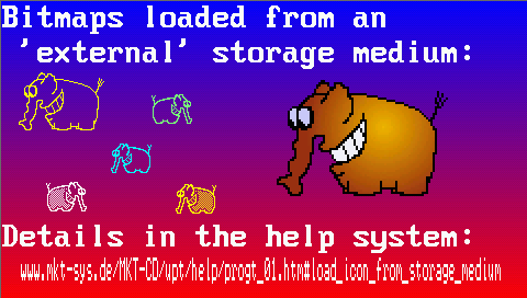
Screenshots from application 'BitmapsFromExternalStorage.cvt', with (left) and without (right) the required files on a storage medium.
For non-existing images ("files not found"), the filenames are displayed instead of the graphics. Click on any image to magnify.
- For coloured icons, i.e. icons imported from bitmaps with 4 or 8 bit/pixel, one of the 16 or 256 possible colours (in the bitmap file) can be used as transparent colour. An example for such a display page can be found in the file arm7_special\transparent_color_bitmap.cvt. The second colour value (which would be the 'background colour' for normal text lines) must be set to -2 (minus two, means "no background colour but transparent"). The third colour value must be set to the colour of all pixels in the bitmap file, which shall appear transparent on the screen later. In the test application, all white pixels (colour number 7) in the wolf spider image appear transparent on the screen (see left screenshow below). Because the "spider2" icon is always painted as the last element (when updating the display), the spider seems to sit on the screen (in front of all other display elements).
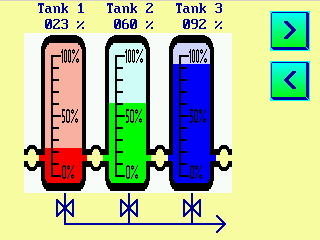
(screenshots from the 'transparent bitmap demo')
See also: Transparent buttons, Overlapping graphics, System Icons (Indicators for Logger, Audio Recorder, Power Supply).
Using Display Lines as Menu Items
Programmed display lines can also be used to implement a simple "menu".For this purpose, set the Flag "This line is a menu item" in the display line properties of a display line definition. This turns a normal "display line" into a "menu item" which can be seleced using the CURSOR keys (or via rotary knob in some cases, or via touchscreen .... see feature matrix).
Next, define what the UPT firmware shall do if the User presses the ENTER key on that menu item. In most applications, this will be a goto-command to an other display page.
- Example:
- g"Menu2" (assuming there is a display page called "Menu2" in your application)
This command has to be entered in the "Var/Expression" column of a display page definition. If you don't know the name of the 'destination' page yet, leave this field empty and use the Menu Link Dialog later to define all menu jumps (when all display pages of your application exist, much easier to use, the goto-command will then be generated automatically !).
You can –additionally- define a ‚hotkey‘ for this kind of menu on the display line property panel.
There are some UPT interpreter functions that give you additional control over this kind of menu:
- mi : returns the line number (index, 0..n) of the current menu item.
-
mm: returns the current menu mode. It may be one
of the following values:
0 = Menu is "Off", that means the menu selection bar is invisible
1 = Mode "Selecting", that means the menu selection bar is visible, the user may move the selection between all "menu items" on the current page using the cursor.
Other "modes" are only valid for numeric edit fields, for example 2 = "editing the value".
There are also some "SET"-Procedures for this kind of menus, which have the same names as the "GET"-Functions:
- mi( <new_item> ) allows setting the "current" menu item under program control
- mm( <new_mode> ) allows setting the "current" menu mode under program control
You may find an example for this kind of menus in the file \programs\NEWMENUS.UPT.
Note: If you use a Display Line as a Menu Item,
you cannot show the contents of a numerical parameter in that line !
Single Bargraph diagram (optional)
All devices with a graphic-capable display support simple bargraph elements. Multiple bargraph elements can easily be composed into more complex displays (using the graphic editor), e.g.:
![]()
Display page with bargraph diagrams as 'tank level' indicators,
using transparent bitmaps as frames in the foreground.
Details here (separate document, bargr_01.htm).
Y(t) and X/Y-Diagrams (optional)
Y(t) diagrams show the chronological trend of one of more signals, e.g.:
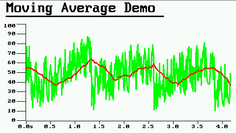
Dual channel Y(t) diagram on a 480*272 pixel screen.
Multi-Line Text Panels (used as "text screen" for the script language)
The backslash-sequence "\panel" defines a rectangular area, which can be used by the script language to display a few lines of text (like a small text display window).At the moment, the multi-line text panel can only be filled by the script language, using the print command .
Without the optional options (in parentheses), the text panel has no visible border around the text area.
The following options can be specified inside parenthesis after the \panel keyword:
- bo=<line width of the outer border in pixels>
-
The outer border is is painted with the display element's foreground colour
.
- bi=<line width of the inner border in pixels>
- The inner border is is painted with the display element's background colour .
Example: \panel(bo=6,bi=2)
defines a text panel with a 6-pixel wide outer border, and a 2-pixel wide
inner border ("frame") around the text area, which reduces the size of the
remaining 'netto text area' by 8 pixels on each edge (upper, lower, left, right).
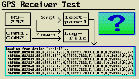
(Screenshot from the script example "GPS Receiver Test")
To turn a display-element into a multi-line text panel, set the display element's type to 'Multi-Line Text Panel' on the page definition tab:
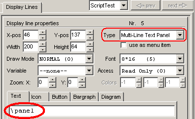
During edit mode, as long as the script has not printed any text into the
text screen buffer, the programming tool will fill the text area with dummy
characters, so you can easily see if the size of the text panel is properly
aligned to a multiple of the font size. All characters in a multi-line text
panel use the same font (as defined for the display element, see screenshot
above).
A text panel can also be used as a control event (for example, react to touchscreen events).
Details and examples can be found in the manual for the script language.
See also : script language (external link,
only works in the HTML-based help system, but not in PDF documents), script:
print, script:
gotoxy, script :
setcolor .
Graphic Panels (displaying script-generated 'Canvas' graphics)
In addition to the text panel element from the previous chapter, devices with script language and a graphic display also support graphic panels. Such elements can be used to show script-generated graphic images on the screen. To place a graphic panel showing a script-generated canvas, use the backslash sequence "\canvas", followed by the name of a 'tCanvas' object that exists in your script.Such 'Canvas'-objects can also be used as 'background' for other display elements, e.g. diagrams. In contrast to imported images ("icons"), the image displayed on a graphic panel is generated at runtime via script. There's a simple example in application script_demos/Mandelbrot.cvt (generates a fractal graphic known as Mandelbrot set).
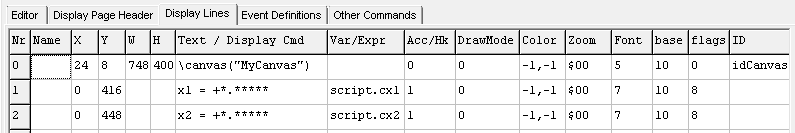
Example for displaying a Canvas object in a backslash sequence.
Here, the script contained a tCanvas-object named "MyCanvas",
which will be set to the specified size of 748 by 400 pixels.
Canvas painting functions.
Inserting other grahic elements on a display page
The "other command"-tab of a page definition lets you insert "special" display commands. It can also be used to see the usage of display commands and event definitions (if the box "show all types of commands" is checked).
Instead, use one of the configurable high-level elements listed below, or (if you really need to "paint yourself"), use the script's Canvas-element instead.
See also:
bargraphs, bitmaps, buttons, diagrams, polygons, analog meters, tables (display elements),
Finding the definition of graphic elements via mouseklick into the LCD simulator.
Overlapping graphics
For some special effects you may place some visible elements (text or graphics) in front of other visible elements.
For example, there may be a large icon in the background and a text display line in front of the icon.

To achive this effect, the icon must be drawn first and the text must be drawn afterwards. The sequence (or "drawing order") is defined by the row number in the screen definition tables.
The first line in the display definition table (line "0") will be drawn first, the second line will be drawn after that and so on.
When using overlapping graphics, you may have to set the option "redraw page completely" in the page definition header, even though this slows down the application a bit. The same applies for moving graphics.
If a graphic element is completely overlapped by another element (like the completely opaque vertical bargrah in the following example, which is completely overlapped by a transparent bitmap) it's sufficient to set the flag 'always redraw this line completely' (instead of completely redrawing the entire page):
(screenshot from the 'Transparent Bitmap Demo',
file arm7_special\transparent_color_bitmap.cvt)
To modify the drawing sequence, press and hold the left mouse button over the leftmost column (labelled "Nr") in the display line definition table, then (with the mouse button still pressed) move the item up or down. Remember, the topmost element in the table is painted first, and the last element in the table is painted last.
See also: Table of contents,
selecting an overlapped element in the LCD simulator,
transparent bitmaps,
transparent buttons,
scripted graphics in the OnPageUpdate-handler.
Touchscreen support
Some devices (e.g. MKT-View II/III/IV/V - see Feature Matrix) are equipped with a touchscreen, but usually with less 'real' keys than older devices - or no real keyboard at all. To keep appications originally designed for devices with a 'real' keyboard useable with newer touchscreen devices, the latter support a 'virtual keyboard' with different (user-selectable) designs.
Multi-Language Applications (and how to realize them)
Multi-language applications can be realized by different means of 'internationalization' ('i18n'):- Duplicate all existing display pages from the 'primary' language, and rename the cloned display pages
by adding a language-indicating prefix or suffix in the Seitennamen, e.g.
"Menu_01" instead of just "Menu" for the main menu in English language,
"Menu_49" for the main menu in German, etc..
- Disadvantage:
- You also need to carefully edit all page-switching commands
in your application ("goto <page-name>) by adding the language suffix/prefix, e.g.
g "Menu_49" to jump into the main menu in German language,
g "Menu_01" to jump into the main menu in English language, etc.
- Advantage:
- Easy to implement and understand, and the tool's display page overview will show all display pages in all languages implemented so far.
- Move (or copy) all character strings from all display pages into a string table, text file, or similar;
whatever you can access with a self written script function (e.g. script.GetText()
in example 'MultiLanguageTest.cvt',
or TranslatePage() in 'i18nDemo.cvt', from where the screenshots shown further below were taken).
To translate all strings on any display page via script, immediately after the original (non-translated) page has been loaded from Flash memory into RAM, implement the OnPageLoaded() in your script (it was designed especially for that purpose), or copy it from script_demos/i18nDemo.cvt (don't forget to tailor the "multi-language string table" in the script for your application).
- Disadvantages:
- Quite advanced for a beginner (you will need at least a bit of programming experience),
and (if all those character strings are moved into a text file or string lookup table)
not easy to test, because simply by looking at the translation table, you don't see
if a translated string still fits into all display elements
(text fields, graphic buttons, etc) on all display pages. So you need to
run the multi-language application, and test all languages, to find out
if everything still fits (not an easy task if you don't know the language, to judge
if a truncated string is still 'sufficiently informative').
Also: Loading a 'translation file' via script at run-time from a file may take a few seconds (once, when booting), and is only possible on devices with the 'extended' script functions unlocked because otherwise, the script doesn't have the file I/O functions for accessing the SD memory card and/or the Flash-Speicher (in pseudo-folder "font_flash" oder "audio_flash").
As an alternative, use a hard-coded translation table in the script itself.
- Advantage:
- Regardless of how many languages you support in your application,
the number of display pages doesn't change because each page itself
is 'multi-language capable' itself. Once multi-language capable, it's easy
to add more features (and display pages) to an existing application,
because you only add a page and it's "program logic" once.

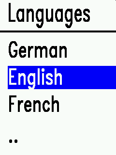
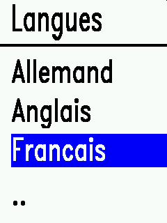
One of the script-translated display pages in script_demos/i18nDemo.cvt.
This simple example uses a 'string translation table' implemented in the script itself.
Thus the application only requires the *.cvt file, no other (external) dependencies.
The "simple" (graphic) editor for display pages
The 'simple' page editor for display pages is located on an extra tabsheet in the programming tool's main window:
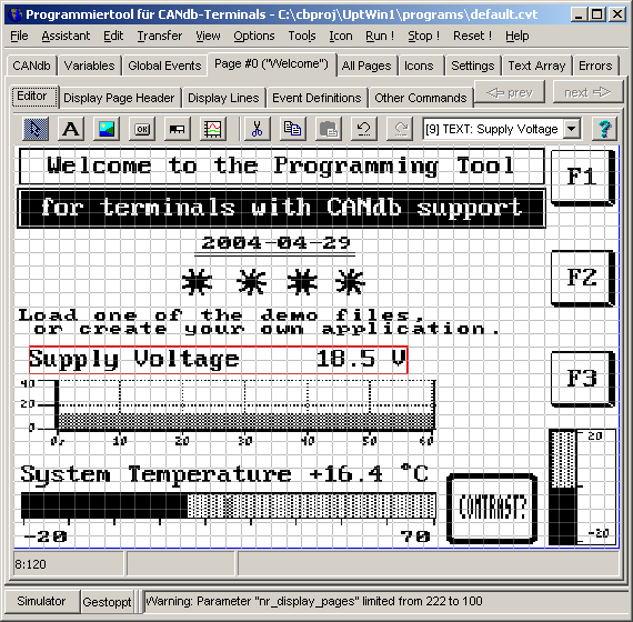
The currently selected object is marked with a red frame in the simulated LCD screen. Multiple objects can be selected and moved, too.
Page editor toolbar
The toolbar of the "simple" page editor contains these buttons :-
 (Arrow or Pointer tool)
: Move or modify items on the screen.
(Arrow or Pointer tool)
: Move or modify items on the screen.
-
Hold the mouse pressed and move it, to modify the element's pixel position.
Use the CTRL-key, or pull a marker frame (start in an empty region on the screen) to select multiple items at once. More on that further below.
Single-click on an item to select it (for cut / copy / paste operations).
Double-click on an item to open a special property editor for it.
Sizeable elements (like buttons) can be resized after being selected by dragging the small square in the element's lower right corner with the left mouse button. The 'sizing corner' then turns orange (instead of the normal red frame around the selected element), which indicates 'element is being resized'. While resizing, the element's upper left corner remains fixed:
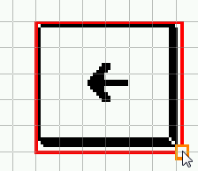
Modifying the size of a display element (here: a button)
by dragging the orange-coloured 'sizing corner' .
-
 (Text tool) : Insert a simple
alphanumeric TEXT line on the screen.
(Text tool) : Insert a simple
alphanumeric TEXT line on the screen.
-
First select this tool (click at the symbol in the toolbar).
Single-click into the screen to place a new text item there.
After that, a special dialog opens where you can edit the new item.
-
 (Icon tool) : Insert an Icon
(symbol; bitmap graphics).
(Icon tool) : Insert an Icon
(symbol; bitmap graphics).
-
Use this tool to insert small bitmap graphics ("Icons") on the display
page.
Note: Before you can insert bitmaps here, they must be imported on the tabsheet "Icons" in the programming tool.
After inserting an icon, you can modify its appearance (colour, zoom, different symbols depending on the value of a variable, etc). Use the arrow tool for this, and double-click on the icon in the editor screen.
-
 (Button tool) : Insert a graphic button.
-
First select this tool, then click into the screen to add a button.
After that, a special dialog opens where you can edit the button.
-
 (Bargraph tool) : Insert a bargraph.
-
First select this tool, then click into the screen to add a bargraph.
After that, you can modify the bargraph in a special dialog window.
-
 (Diagram tool) : Insert a diagram.
-
After selecting this tool, click into the screen to add a diagram.
-
 (Insert Other Objects) :
Opens a sub menu with other 'insertable display elements'
(Insert Other Objects) :
Opens a sub menu with other 'insertable display elements'
-
Those less frequently used elements include tables, polygons,
analog meters ('needle instruments'), etc.
-
 (Cut tool) : Cut out the selected
item.
(Cut tool) : Cut out the selected
item.
-
First select the item which you want to remove (with the Arrow tool),
then select the "Cut" tool (scissors).
When cutting, the selected item is copied into an internal clipboard-like memory, but this is not the windows clipboard.
-
 (Copy tool) : Copy the selected
item.
(Copy tool) : Copy the selected
item.
-
First select the item which you want to copy (with the Arrow tool),
then select the "Copy" tool.
The selected item is copied into an internal clipboard-like memory, but this is not the windows clipboard.
-
 (Paste tool) : Paste
item into selection.
(Paste tool) : Paste
item into selection.
-
First select the item which you want to overwrite (with the Arrow tool).
If you don't want to overwrite a selected item, select nothing.
The item stored in the internal clipboard-like memory will be pasted to the screen.
If an item was selected (marked with a red selection frame), it will be replaced with the "pasted" item.
If no item was selected, the item will be inserted at the position of the insert cursor, which is marked with a small red dot.
The insertion cursor can be set (before inserting an item) with a short click into a non-occupied screen area.
After inserting an element, the insertion cursor will be moved down (or right, at the bottom of the screen), depending on the size of the object which has been inserted, so that there will ideally be no overlap. This way, it's quite easy to fill a page with equally spaced items.
-
 (Undo tool) : Undo recent
operation(s).
(Undo tool) : Undo recent
operation(s).
-
Click this 'UNDO'-button to undo the recent operation.
In the page editor, up to 20 (?) operations can be undone, because they are saved in an undo-history.
Caution: If you exit from the current page in the editor, the changes cannot be "undone" anymore !
-
 (Redo tool) : Redo recent
undo-operation(s) aka "un-undo".
(Redo tool) : Redo recent
undo-operation(s) aka "un-undo".
-
Click the 'REDO'-button to undo the recent und-operation.
In the page editor, up to 20 (?) undo-operations can be undone, there is an extra buffer for this.
Caution: If you exit from the current page in the editor, the changes can neither be "undone" nor "redone" anymore !
The selected object is marked with a red frame in the drawing area.
To move or copy a group of objects, use the 'Arrow / Pointer' tool
to select multiple objects. Hold the CTRL-key pressed, and click on each object
which shall be added to the selection.
Alternatively, first move the mouse (pointer) into an empty area, close to the
upper left corner of the first to-be-selected object. Then press and hold down
the left mouse button, while pulling the mouse from the upper left to the lower right corner
of the selection area. This spans a shaded rectangle over the marked items as shown below:
(Screenshot of the 'simple graphical editor' with multiple objects selected via mouse; left mouse button still held down)
When releasing the mouse button, the shaded rectangle (spanned with the mouse) disappears,
but all objects covered by it remain selected.
To move the selected objects on the screen, grab one of the selected items
with the left mouse buttons (otherwise, clicking outside the selected objects
de-selects all), and -with the left mouse button held down again-,
move the selected object(s) to the new position.
If multiple objects are selected by red frames, 'Copy', 'Paste' and 'Cut' applies to all of them.
So you can quickly copy a block of multiple objects from one display page to another.
The combo box in the editor's toolbar allows you to select individual display elements (in addition to selecting them with the arrow tool). This may be necessary for example, if a display element is completely obscured by another, and cannot be selected with the mouse directly.
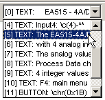
Selecting a single object in the drawing area (with the arrow tool) will also
select that object in the combo box shown above.
The entries in the combo box can be interpreted as follows :
[line number] ELEMENT-TYPE : element-text
Example:
[5] TEXT : The EA515..
- which means:
-
The currently selected display item is defined in line number 5 (an array-index;
numbering starts at zero);
the item is a simple TEXT (alphanumeric);
the display text begins with the string "The EA515..".
Graphic controls can be aligned to an 8 * 8 pixel grid. To show this grid, or let a coordinate snap to the grid, select "Option"..."Page Editor" in the programming tool's main menu. If the option "Snap coordinates to 8*8 pixel grid" is active, the upper left corner of an object will be aligned to the nearest grid point when moving the object with the mouse.
At the time of this writing, only the following display elements were supported by the "simple" page editor:
- TEXT : simple text, with or without variables (use asterisks as placeholder characters). Can be edited in a special dialog.
- ICON : small bitmap graphics ("symbols")
- BUTTON : graphic button (details in 'btns_01.htm').
- BARGRAPH
- DIAGRAM : Y(t) or X/Y-Diagram (details in 'diagr_01.htm').
- TABLE : Table (Control- or display element with multiple rows and columns)
- POLYGON: Polygon (lines, or shapes like rectangles, triangles, etc; editable "point by point").
- METER: an analog meter ('needle instrument')
Special functions like graphic interpreter commands
or script-generated text
are not supported by this editor (they must be edited 'as text').
The functions Copy / Cut / Paste, and the 'Property' dialog for a certain
display element can also be launched through the graphic editor's context menu (right mouse button).
Dialog box for alphanumeric display elements
Double-clicking on a normal alphanumeric display element opens the dialog shown below:
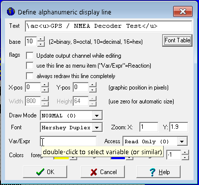
In the 'Text' field, you can enter normal static text, but also backslash sequences, placeholders for digits (*,#,0) and sign (-), HTML-like tags for bold, italic, and underlined text as specified in chapter 'page definitions' .
Creating and modifying polygons with the graphic editor
Polygons may be single lines, line segments, grids, squares, triangles, and many other geometric shapes. Unlike bitmap graphics, polygons (like "vector drawings") can be easily scaled for any screen resolution. The number of "points" per polygon is limited (by the maximum length of a "definition line"), thus complex 'drawings' may have to be composed of multiple polygons (each in an own definition line).With a max. length of 500 characters per definition line, and 6 characters per coordinate, expect up to 80 points per polygon.
- For experts and advanced users:
- The graphic editor generates an "\li" backslash sequence ("li" = "lines"), followed by the coordinates of all points in the polygon.
The argument list (after "\li") may also contain graphic elements like polygon(), polyfill(), etc.
The syntax of "\li" is described here (including the use of commas and semicolons to control drawing lines between points).
Like any other display element, a polygon can also be edited 'as text'.
To do that, mark the polygon in the editor, right-click into it, and select 'Properties' in the context menu shown further below.
Button in the graphic editor's toolbar |
|
|
Menu of the graphic editor to insert 'other elements', |
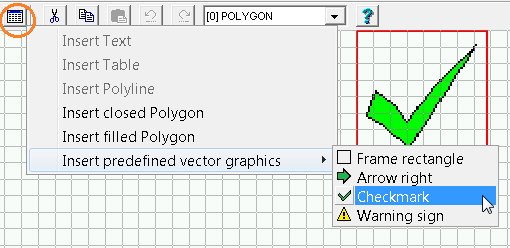
After selecting one of the polygon objects or predefined vector graphics from the menu, click into the drawing area to specify the position of the upper left corner of the new graphic element.
Later, you can adjust the size of the new polygon (etc) by dragging the lower right 'sizing corner' as already described.
Points, lines, or polygon vertexes can be added or deleted as described further below.
A double click into a polygon's drawing area toggles between "Move or resize the entire object" and "move, delect, insert single points". In this state, all points of the polygon are marked as small red squares. These small squares can be grabbed with the mouse, and moved within the drawing area:
| ⇔ |
|
Polygon in editor state 'Move / Resize' | Polygon im editor state 'Edit Points' |
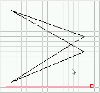
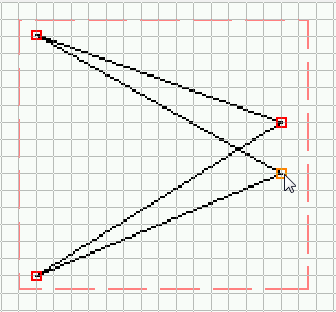
Less frequently used functions of the graphic editor are available in the context menu.
To open the context menu shown below, right-click into an already selected object. The appearance of the menu may depend on what was actually clicked:
|
Context menu of the graphic editor with options to edit a polygon |
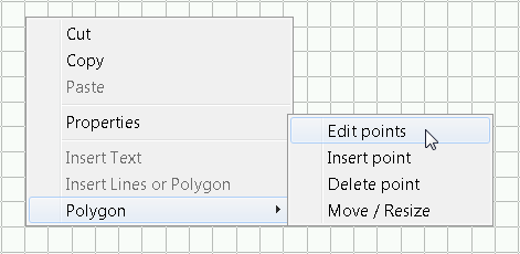
Examples for lines, polylines, polygons using the '\li' command
Most of the examples shown below were taken from the application programs/line_art.cvt.Some commands require a drawing area of at least 100 * 100 pixels. Note that all coordinates within the argument list are relative to the display-element's own position.
- Simple line with start- and endpoint taken from variables (requires manual input 'as text'):
\li(x1,y1, x2,y2)
- Four-pixel wide line (parameter "w"=width)
\li(w=4, x1,y1, x2,y2)
- Two lines (note the semicolon as separator between coordinates with "pen up")
\li(8,8, 8,88, 88,88; 16,16, 16,80, 80,80)
- Closed, but not filled polygon (here: triangle)
\li(polygon(0,99, 50,0, 99,99))
- Filled polygon with a 'thick border' :
\li(polyfill(w=4, 5,95, 50,5, 95,95))
- Filled polygon without border (no lines around the filled area) :
\li(polyfill(5,95; 50,5; 95,95))
See also: Polygons in the curve area of a diagram, general '\li' syntax, rotated text using vector fonts.
Back to the table of contents
Creating an analog meter (needle instrument) with the graphic editor
Since 2017-08-01, analog meters and similar 'instruments' don't need to be created with polygons anymore.Instead, they can easily be dropped on a display page like any other graphic widget. Parameters are customized as a property list on the programming tool's display page definitions tab:
Outer Shape
Rect: Rectangular instrument (e.g. "voltmeter"), Round: e.g. "tachometer".
Arrow Type, Arrow Colour
appearence of the main indicator (needle, arrow, compass pointer, etc).
Start- and End angle
Defines the angle range of the instrument's moving 'needle' or 'pointer',
using the 'compass' angle system shown further below.
Scale start value
Value for the scale's lower endstop. Corresponds to the 'start angle' for the indicator needle.
Scale end value
Value for the scale's upper endstop. Corresponds to the 'end angle' for the indicator needle.
Arrow2Value, Arrow3Value
Numeric expressions to be displayed by the instrument's 2nd and 3rd arrow.
The first arrow's value is taken from the element's associated 'Variable' / numeric expression.
Examples for analog meters in different sizes and styles can be found in the 'Analog meter test' (demo application in file analog_meter_test.cvt):
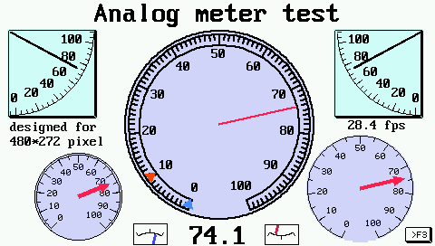
Screenshot from application 'analog meter test'
The angle range of the instrument's moving pointer (needle) is entered as start- and end angle in the property list. Angles are specified in degrees as on a compass, as shown in the image below.
For convenience, negative angles are also accepted (-90° will be the same bearing as +270°, i.e. "points to the west").
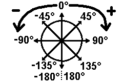
Bearings on a compass (in degrees)
Examples:
Analog voltmeter: StartAngle=-45 (or 315 degrees), EndAngle=45 .
Round tachometer: StartAngle=-135, EndAngle=135 .
Analog clock (see example shown further below): StartAngle=0, EndAngle=360 .
For round instruments, the pivot (rotating axis) is always centered.
For instruments with rectangular shape, the pivot is optimally placed for the
largest possible circular path of the indicator's tip. Thus the position of the pivot depends
on the angle range. For small ranges (like the "Voltmeter" with StartAngle=-45, EndAngle=45°),
the pivot point may even be outside of the visible area.
Besides the main arrow (or needle), two additional indicators (pointers, needles, markers) can be displayed
inside the analog meter. The position of these extra indicators may be a simple numeric constant (value),
variable, or even a numeric expression to scale them properly.
To insert an analog meter on a display page, right-click into the LCD simulator window,
and select 'Insert analog meter' ('Zeigerinstrument einfügen'). As for any other display element,
the specific properties can be modified in the right half of the programming tool's main window:
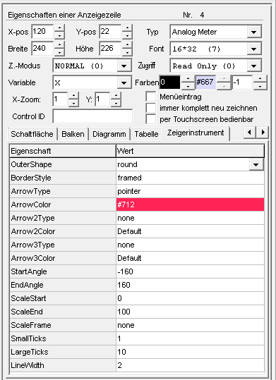
Property panel for an analog meter (Zeigerinstrument)
in the programming tool's display page editor
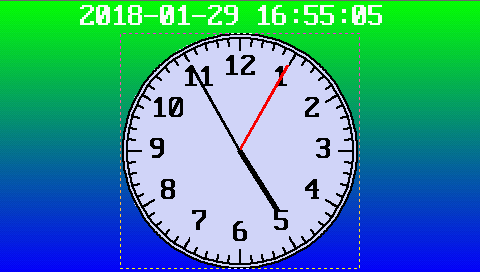 The 'analog clock' shown on the right is a screenshot from sample application 'programs/analog_clock_480.cvt'.
The clock consists of a single pointer instrument (with three pointers), angle range 0 to 360°, value range 0 to 12.
Hour-, minute-, and second-pointer are defined as follows:
The 'analog clock' shown on the right is a screenshot from sample application 'programs/analog_clock_480.cvt'.
The clock consists of a single pointer instrument (with three pointers), angle range 0 to 360°, value range 0 to 12.
Hour-, minute-, and second-pointer are defined as follows:| Pointer | Arrow Type | Numeric expression (displayed values) |
|---|---|---|
| Seconds | thin_line | rtc.se * 0.2 |
| Minutes | thin_line | rtc.mi * 0.2 |
| Hours | short_line | (rtc.hr%12) + rtc.mi/60.0 |
In the numeric expressions shown above, the 'rtc'-functions retrieve the current time (second, minute, hour) from the real time clock. By multiplying those values with suitable factors, all three values are converted into the same value range (here: 0..12), because a single instrument uses the same value range ('ScaleStart' to 'ScaleEnd') for all pointers.
Back to the table of contents
Defining Events – overview
An "event" is the occurrence of a special situation that you want to handle in your terminal program.An event can be:
- User presses or releases a certain key on the terminal
- User turns the optional rotary encoder knob
- The value of a variable exceeds a certain value (may have been received via CAN)
- One bit of a variables is set to a certain value
- and more combinations.. see event definition language in the next chapter.
For every event you also have to define a special "event reaction". A reaction can be defined as a sequence of interpreter commands .
Possible reaction methods are:
- Switching to an other display page
- Setting a certain variable to a certain value (which may be sent via CAN)
For the definition of events we use a simple event definition language, but you may also define events for a display page by selecting them from list.
Events may be defined...
- "global", that means not depending on the current display page;
- "local" on a display page, which means only active when this page is the current page.
To define events, you can use the event-definition window explained in the next chapter. Advanced users will enter the interpreter code directly, others may prefer the 'global event catalog' .
Related topics:
- interpreter commands
- numeric expressions
- Event Handling in the Scripting language (for devices with 32-bit CPU, for more advanced control)
Defining Events - the definition window
To define events and reactions, you may use this definition window (which is almost the same for global and local events):
The propery-panel on the right shows more detailed information about one single event definition.
You may edit the properties of a display line in the table or on the property
panel, the information will always be updated on both parts.
A single breakpoint can be set on a certain event
by checking 'Set breakpoint on this event' on the property panel. It will fire whenever
the condition for that event becomes TRUE, before actually executing
the reaction.
To execute a single step
(after being stopped by a code- or data-breakpoint),
press function key F11 on the PC keyboard. There is no button or menu item for this.
The "Add event" and "Add reaction"-Buttons on the property panel open special
dialog windows, which can be used to define event definitions or reactions
(especially if you are not familiar with the event definition language).
To inspect the current value of variables or certain expressions in an event definition table,
simply point the mouse over the cell (without clicking). If the interpreter
can evaluate the 'word' (delimited by spaces or other special characters)
under the mouse pointer, the result will be displayed in the status line
at the bottom of the main window.
During a simulator run, the background colours
of cells in the event definition table indicate which events (conditions)
are currently active (condition = TRUE), and thus which reactions have been
invoked during the last update cycle (as far as the GUI update speed permits).
This is similar as the 'Condition Actions' in the CAN-Simulator:
- Light green background :
The condition in this line is (or was) TRUE, and the reaction has been executed without errors.
- Yellow background :
Indicates the next to-be-executed line in single-step mode, e.g. after hitting a breakpoint as explained further above.
- Light red background :
There was an error when evaluating the event (condition), or when executing the reaction (command line).
Defining Events - the definition language
An "event" is the occurrence of a special situation that you want to handle in your terminal application. To define such an event, you may use this event-definition-language which uses the UPT's command interpreter to analyze numeric expressions.- Note:
-
The programming tool may display some of these events in a longer, human
readable form, like
page_enterinstead of "pe".
A few simple expressions are listed below:
| Event-Type / expression |
Parameter (if required) |
Description |
| kd | key-name | user has pressed a key |
| ku | key-name | user has released a key |
| kb | key-name | buffered keyboard
event. The specified key will be removed from a buffer ! |
| kh | any key has been hit (system keys too) | |
| kc | reads and removes a system key code from a buffer. | |
| kcb | reads the code of the last pressed key, but does not remove it from a buffer | |
| cb | CAN-Error: Bus Off See also : 'cs' (CAN Status) |
|
| ce, alias ce0 | Severe CAN-Error on the first CAN port | |
| ce1 | Severe CAN-Error on the second CAN port | |
| cw | CAN-Warning | |
| ch | CAN-hardware fault | |
| co | CAN-Error: Overflow | |
| ct | CAN-Error on transmit See also : 'cs' (CAN Status) |
|
| else | Returns TRUE, if the previous Event-condition was FALSE. Only supported by firmware compiled 2012-10-15 or later ! Example |
|
| t0 ... t3 | User-timer ( nr. 0...3) has run off | |
| ti_ms>1500 | Over 1500 milliseconds elapsed since power-on | |
| pe alias page_enter |
Current page has just been entered (Page Enter) | |
| pq alias page_quit |
Current page will soon be left
(Page Quit). Like any other page-event, this event can only occurr on the currently 'visible' page, not on any other page ! To implement a centralized method to react on 'any kind of page-switch' (regardless of the current display page number), we highly recommend to use the Script Language ("OnPageLoaded"). |
|
| pr alias page_redraw |
Page Redraw, the current page must be redrawn. Occurs together with "pe" or after calling cls (=clear screen command), or when setting display.redraw in a script. | |
| pdo[N].rcv | A PDO telegram has been received . | |
| rot.l, rot.r, ... | The rotary encoder ("knob") has been turned | |
| syn.rcv | A SYNC-Telegram has been received . | |
The terminal's interpreter evaluates the event definition as a boolean expression. You may also use more complex numeric expressions as event definitions.
If the result of an event-definition (or expression) is non-zero, the system interpreter executes the corresponding reaction method. An event reaction method is (internally) coded a string of interpreter commands.
Example: Modify the background colour of a display element (from 'Auslieferungstest.cvt'):
   Event (condition)                 Reaction
   (sys.vsup<120)||(sys.vsup>260)    dis.VSup.bc = (ti&8)?7:4 : REM flashing supply-voltage warning
   else                              dis.VSup.bc = white      : REM no voltage warning
See also: Overview of numeric interpreter
functions.
Global and Local Events
You may define global events for situations that are independent of the current display page (they are always "active", no matter what the "current page" is).- For example, you may wish to "call" a certain display page whenever there is a severe error on the CAN-Bus. This can be achieved by the following example:
-
Event-Definition: ce (which means: "if there is a Can Error"...)
Reaction: c"CanError" (which means: ... call the page named "CanError")
Define this Event and it's reaction method on the "Global Event" page, so you don't have to define it on every used page (remember, the number of lines on a page is limited !).
There are some rules for global events that you should use:
- Use global events for all events that would otherwise be equal on every page definition.
- Don't use display output commands in the reaction methods of global events, because this might "interfere" with the screen output of some of your pages.
- If you defined a certain event as a global event (like "ce" in the example above), you should not define this event again as a "local" event on any display page. However, defining an event twice does not hurt the event handler. If many event definitions are TRUE at the same time, all their correspondig reaction methods are executed.
Local events always belong to a certain display page (they are only checked if that display page is visible). In most applications, local events react on keyboard actions and switch to other pages.
Simple GLOBAL events can be selected from the global event catalog (a special dialog which can be opened from the Global Events page).
return to the event definition overview
Assistants and dialog-based utilities
Assistant to create simple display applications
The dialog-based assistant described below can (but doesn't have to) be invoked from the main menu, via 'Assistant' .. 'New program, simple' or 'New program, universal'. The assistant will lead you through various steps for creating a completely new display application. In many cases, you won't use it, but rather 'recycle' an already existing application and adapt it as necessary.
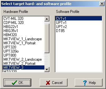
(Screenshot 'Select target hard- and software profile')
- Technical brackground:
- For many devices, for example MKT-View II, there is only one hardware profile, which contains
the screen resolution, colour model, and much more. In addition there are multiple
possible software profiles (for the same hardware), depending on the loaded firmware.
For example, you can select a software profile for a CANopen device (UPTv1=DS301 V3, UPTv2=DS301 V4); or (for all devices withoutCANopen-Firmware, but instead 'CANdb') select 'CVTv1' as the software profile (CAN-View-Terminals, z.B. MKT-View II mit Firmware #11314).
The programming tool may ask you to use a different tool; because (for example) the programming tool for devices with 'CANdb' (DBC, automotive) doesn't support CANopen itself, and thus will not be able to load the display application into the device via CAN.
In the next step, the assistant will ask for the number of display pages for your new application:
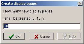
(Screenshot 'Create Display Pages')
Select how to switch from one display page to another, using the 'global event catalog':
Variable Selection Dialog
This dialog can be used to replace references to VARIABLES on a DISPLAY PAGE. You can open it by selecting the item "Check & Modify VAR/SIGNAL references" after right-clicking into the display line definition table, or from the tool's main menu: "Check and modify variables on current page". For example, click the "More.." button on the tabsheet "display line definitions"
(Screenshot "Buttons on the display line tab")
(Screenshot of popup menu "display lines")
(Note: This dialog may appear in other situations also, for example when using the assistant).
The panel on the right side displays either a list of all existing variables, or an overview of all Nodes+Messages+Signals which may have been loaded from a CANdb file earlier (only for devices which support CANdb signals). For terminals with CANopen, there will be an other tab on the right panel showing a list of CANopen variables in the local object dictionary (more details in another document).
First select the variable you want to replace , then -on the right side- select a variable, a signal, or a CANopen object which shall replace the old connection. If you select a CANdb signal from the threepart list (Nodes, Messages, Signals), a new variable will be created automatically, if no variable exists for this signal yet.
The "type" column in the table indicates if a variable is connected to a signal ("Sig") or if its a "normal" variable (which is not connected to a communication channel). If "Sig" is followed by a question mark, the original signal definition does no longer exist in the CANdb definition table (on the tabsheet "CANdb"), most likely because the table has been erased manually because it was considered "secret". This does not affect the normal operation of the terminal as a display.
For terminals which support the script language, the Script tab (not shown in the screenshot above) contains a list of global script variables. Picking a script variable from that list will generate the prefix 'script.' before the name, so the display interpreter knows that this is not a 'normal' UPT display variable. Local script variables cannot be accessed by the display interpreter, thus they are not shown in this list.
If the option "select new line automatically" is active, the selection bar of the display definition table (=blue mark in the table) will switch to the next line whenever you click on an entry in the list on the right panel. This minimizes the amount of mouse-clicks needed to redefine a complete display page.
The option "replace name in display text" does this:
If the NAME OF THE VARIABLE is part of the old menu text, it will automatically be replaced with the name of the new variable.
- For devices with CANdb functionality only:
-
If you have a large number of SIGNALS, it may be difficult to find the required
signal, when you don't know the exact name of the NODE and MESSAGE. There
is a global search function for SIGNAL NAMES through all NODES and MESSAGES.
Activate it by right-clicking into the NODE LIST. A popup-menu appears; select
"Find Signal" and enter the signal name. The search function is not
case-sensitive, so don't care about upper or lower case letters when entering
the search string.
Because different messages could carry different signals with equal signal names, the search can be continued at the current position in the database ("find next occurrence of XYZ").
See also:
return to the table of contents
Menu Link Dialog
This dialog of the programming tool can be used to assign 'jump destinations' for all menu lines which are defined on a single display page. It will open automatically when the 'check all pages' detects a non-existant menu link, or from a popup menu on the display page definition screen.
The menu selection (=blue mark in the table) will switch to the next menu
line after selecting a new menu (which minimizes the number of mouse-clicks
if you want to re-define all menu links on a display page). You can also
select another menu line by clicking into the table.
- Note:
- Modifying the text of menu lines, or the graphic appearance, is not the task of this dialog. Use the display definition screen to change the displayed text, font, graphic location, etc.
If there is something wrong with the menu definition, an error message in red color appears on the dialog screen. Usually, the reason is a menu link to a non-existing display page. All invalid menu destinations are also marked in red color in the table.
There are some checkboxes in the lower right corner of the menu link dialog:
- Select new line automatically
- Enables or disables the automatic selection of a menu line (to minimize the number of mouse-clicks)
- Replace (variable-) name in menu (-text)
-
If the name of the destination page is embedded in the menu text, it will
automatically be replaced with the name of the new destination page. If the
name of the destination page was not part of the menu text, the menu text
will not be changed.
Note: To EDIT THE MENU TEXT, use the display page definition tab.
If the menu link dialog has been opened from the display page overview, you can use the "previous" and "next" buttons to modify the menu links on another display page.
After you have selected destination pages for all existing menu lines, click "OK" to accept the changes.
return to the table of contents
Assistant 'Check & correct all display pages'
When 'recycling' display pages from an old application for a new purpose,
problems may occur if (for example) the copied display page contains references
to variables that have not been defined in the new application yet;
commands to jump to another (not-yet-existing) display page, aka "broken links", etc.
To spot such problems more easily, in the programming tool's main menu,
select 'Assistant', option
Check & correct all display pages .
The programming tool then scans all pages (and all display definitions on those pages)
for errors like:
- References to undefined / deleted display variables on a display page
- Placeholders for not yet defined variables on a display page (e.g. <SelectMe> instead of a proper variable name)
- Jump to a display page with unknown name or 'number' (e.g. a 'broken menu link' / "goto")
- Errors in numeric expressions (i.e. if the to-displayed value isn't a simple variable, but 'calculated', with a bug in the formula)
Depending on the type of the error, and the position (page, definition line, column),
the corresponding table cell will be coloured (on the tabsheet "Page #").
Errors like references to non-existing varibles will have a red cell background,
warnings (e.g. placeholders like '<SelectMe>) are marked with a yellow background.
Besides that, if necessary, this assistant may automatically invoke the
dialog to select variables on a display page.
Global Event Catalog (deprecated)
The unexperienced user may select a few global events from this 'catalogue':
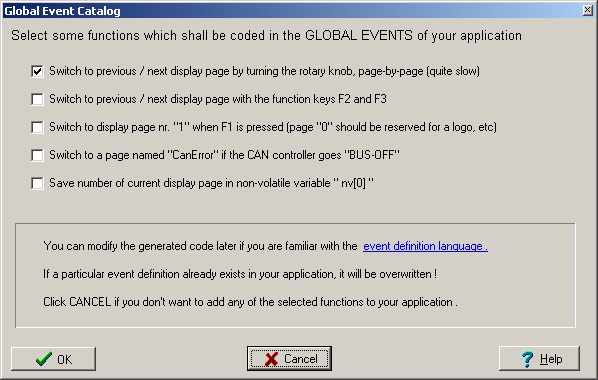
(Screenshot 'Global Event Catalog')
- switch from one page to another
- switch to a certain page if a serious CAN-BUS error occurrs
- ...
See also:
If the 'global event catalog' was opened from the 'new application-assistant, this was the last step guided by the assistant. Before uploading the application into the programmable device, you will usually check the displayed variables or fine-tune the display using the page editor.Display Page Overview ("all pages")
The Page Overview tab shows an overview of all pages that are currently defined in your terminal application.You may double-click on any of the page overview icons to switch to the page definition sheet, where you can modify the page's contents.
A single click on one of the pages on this screen selects it for the following actions. The selected page is marked with a colored frame.
Clicking on one of the pages on this screen with the right button opens a popup menu which allows you to...
- insert a new, empty page (before the selected page)
- delete the selected page
- copy & paste a page (to modify the page sequence)
- check all menu links on the selected page
Options for the display page overview:
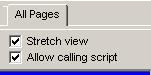
- [v] Stretch view
- The display page overview uses streched (or compressed) preview-images
with a fixed size (usually smaller than the original display resolution).
You won't see each pixel with this option, but more pages will fit on the screen without scrolling.
- [v] Allow calling script
- Without this option, no script functions are called when generating the preview.
This improves the speed of the update, especially if the script must do a lot of work
(for example, read the actual display text from a network, or from a file).
Instead, when generating the preview for a display element which uses a script to retrieve the text (string), the preview will show '<generating preview>'.
Depending on your script, this option may also avoid side-effects like increased network traffic.
See also: display page definitions,
table of contents
The Icon import screen
This screen of the programming tool is used to import and browse icons (bitmaps) for an application.
From the main menu, there is also the possibility to create a new (empty) icon with a certain size (Icon...Create New).
You can modify the icon pixel by pixel (click into the image on the right) but it's easier to use an image editor like "Paint".
The name of the bitmap file must be a valid DOS filename, because the internal storage of huge objects may be based on a file system similar to DOS . For that reason, make sure the filename is compliant with the following guidelines (which applies to other names, too):
- The name must begin with a letter (a..z, A..Z) .
- The name must be 1 to 8 characters long .
-
The 2nd to 8th character must be one of the following:
a..z, A..Z, 0..9, or _ (underscore character). NOTHING ELSE. Especially no spaces, even though some think it's cool to allow spaces in filenames. WE DON'T.
In older devices with only 256 colours (e.g. MKT-View II), only bitmaps with 1, 4, or 8 bit per pixel could be imported; thus monochrome, 16-colour, or 256 colour bitmaps. The colour palette is always fixed, so don't expect the image to look exactly the same way as in your image processing software with 16 million colours ("true colour").
For experts:
-
The tabular overview with all imported icons/bitmaps list names,
width / height (in pixels), and the bitmap type / colour depth.
The decimal codes for these 'bitmap types' are the same as used
when embedding imported bitmaps 'as text' in the *.cvt- or *.upt file:
- 0 = monochrome (one bit per pixel)
- 1 = 16 colours, four bits per pixel, only standard colours (colour indices 0 .. 15)
- 2 = 256 colours, eight bits per pixel, no palette but format RGB-3-3-2
- 3 = 256 colours, eight bits per pixel, reserved for bitmaps with an individual colour palette
- 4 = 65536 colours, 16 bits per pixel, format RGB-5-6-5
- 1 = 16 colours, four bits per pixel, only standard colours (colour indices 0 .. 15)
- 0 = monochrome (one bit per pixel)
-
The 256-colour palette uses 2 bits for the blue channel, 3 bits for the green
channel, and 3 bits for the red channel. Some image conversion tools (like
IrfanView) can optimize "high colour" or "true colour" image for such a palette,
using a smart method like Floyd-Steinberg dithering.
Such methods produce better results than the simple import filter
(implemented in the programming tool), which always picks the closest
colour from the device's 2+3+3-bit RGB palette.
- The process of converting an image with IrfanView, using an optimized palette, is described in the file 'readme_irfanview.txt' located in the 'icons' folder of the programming tool.
-
Since November 2021, the 'remaining free space' (number of kBytes in Flash)
displayed in the lower panel of the icon import screen must be taken with
with a grain of salt, because many targets (like the MKT-View III and IV)
internally compress certain bitmaps to reduce their memory footprint.
The only reliable indicator for the target's remaining Flash memory space is in the target itself; it can be invoked from the Setup/System Menu via Diagnostics .. Storage Directory. The occupied and remaining internal Flash memory is displayed in the bottom line (below the list of stored items), e.g.
Used: 672; unused: 357 kByte .
-
In some devices (with sufficient code memory), the list of imported
icons, and their individual memory consumptions can be inspected by selecting
the line with 'Type=ICON' in the 'Storage Directory' and pressing ENTER.
This opens the 'Icon Browser', where all Icons can be listed (and optionally
displayed as graphic), along with their compressed and uncompressed sizes.
After importing all required icons (as explained above), the icons can be used in the display-application as described here .
In newer devices (e.g. MKT-View III), instead of embedding icons directly in the application (*.cvt / *.upt), they can alternatively be loaded directly from a suitable storage medium, which saves a lot of space in the *.cvt / *.upt file.
See also (related subjects) :
"Boot Screen" (graphic shown immediately after power-on, not part of the *.cvt-application),
Canvas objects (graphics generated via script at runtime).
Reserving memory for icons (and other special features)
In most display terminals, Icons, Pages and Text Array share the same memory inside the user programmable terminal. But there are severe differences between older and newer devices (also depends on the firmware compilation data / revision number ! ).In old devices with 8- or 16-bit-CPU (like MKT-View 1 / MKT-View "Plus", memory had to be reserved for icons before they could be imported from bitmap files.
Which kind of Flash memory management is used in a certain device can be checked after selecting the target (which not only updates the display size, but also some information about the target device's firmware) on the 'Settings' tab under Terminal Constants / Flash memory management:
- static (very old)
- All display pages have the same size in their flash storage (a simple array),
icons are stored in an extra memory area (or even a separate Flash device).
This method was only used in very old devices with an 8-bit CPU, e.g. "UPT-515".
- static, shared (old)
- Display pages still occupy a fixed size in Flash, but share the same
memory area with icons, text arrays, display pages, etc.
This method was only used in old devices with a 16-bit CPU, e.g. "MKT-View I".
- flexible, shared
- Display pages only occupy as much Flash memory as needed, depending on the number of elements
on a page (and their 'complexity', i.e. length of the definition line.
All kinds of strings are stored with a variable length ("as short as possible",
as far as CPU-dependent memory alignment permits).
Icons, display pages, text arrays, scripts, variable declarations, extracts from
CAN databases all share the same Flash memory.
This method is used in all newer devices with a 32-bit CPU, e.g. "MKT-View III / IV / V".
Memory usage for older devices (with 8- or 16-bit CPU, or firmware compiled before 2009-08-05) :
In devices of this class, all display pages have a fixed size in (FLASH-)memory. If a display application consists of the maximum number of display pages, there will only little memory left for other objects ( like text lines and icons).Reducing the number of pages increased the amount of memory available for icons.
Because devices with this 'static' memory distribution are long out of production (MKT-View I, MKT-View "Plus"), details have been removed here, and can only be found in archived versions of the programming tool.
Flexible memory usage for newer devices (with 32-bit CPU)
For newer devices, the method of storing display pages, text array lines, icons and many other objects in FLASH memory has been completely rewritten, making use of linear 32-bit memory pointers, which were not available for 8- and 16-bit stoneage controllers.Now each object only occupies as much memory as necessary (for experts: Older devices used array, new devices use linked lists in memory). Display pages with fewer, or shorter lines use much less memory than they did in oder devices. So usually(!), there will always be enough storage memory, even if your application needs "many" pages and "many" text array lines (whatever "many" actually is.. 255 pages, and 4096 text array lines). You can be generous with the max. number of display pages, and the max. number of text messages (text array lines) in the dialog box shown above - even if your application will never need so many of these objects.
The programming tool will guesstimate the amoung of remaining "free" memory in the terminal, but it needs to know some parameters about the terminal to do this properly. This includes the maximum usable FLASH size and a few other hard- and firmware specific details, which are also saved in the *.CVT or *.UPT file.
When migrating (or "upgrading") from one class of devices to another (for example from "MKT-View" to "MKT-View II" or later models) you can modify this information (in an already existing application) with a suitable text editor, or with the programming tool on the 'Settings' tab which as explained in the next chapter.
To estimate the memory sizes correctly, the programming tool needs to know the following parameters :
-
Icon Memory Shared (which is the parameter "t icons_shared"
in the *.CVT / *.UPT - file) :
0 = Icons use their own FLASH memory sector; display page sizes are static ( "old" terminals / firmwares, MKT-View, all 16-bit CPUs)
1 = Icons and display pages use a common FLASH area, display page sizes are static (for example "UPT515")
2 = Icons, display pages, and others use a common FLASH area, all objects have a variable size in FLASH-memory (only for 32-bit CPU,
for example "MKT-View II", "MKT-View III", "UPT 320", and other devices with 32-Bit-CPU (ARM-7 or Cortex-M); firmware compiled in August 2009 or later) -
Max. Data FLASH Size (which is the parameter "t max_free_mem_kbyte"
in the *.CVT / *.UPT - file) :
Spezifies the size of the FLASH memory usable to store display pages, variable definitions, text array lines, icons (images), and other objects. A different part of the FLASH memory is used for the terminal's firmware and operating system; making the available "free" memory size depending on the hard- and firmware. For example, in the "UPT 320" (terminal with 5.7" TFT display, 320*240 Pixel) with firmware #11352, there were 896 kByte FLASH memory avaiable for the user application ("display program").
| CANdb Display Terminal (...) Compiled: Aug 5 2009 (...) Loading .... ( unused : 761 kByte ) |
A similar value should be displayed by the programming tool on the Icons tab, near the Icon Memory button.
If the readings differ by more than a few kByte, the parameter "max_free_mem_kbyte" in the *.UPT or *.CVT-file may be wrong (because it was copied from an application for a different target). You can fix this, as explained above, using a text editor or by reading back the application from a "real" terminal (because in this case, the programming tool and the terminal can communicate directly with each other, so the tool has the chance read a few parameters from the target device --- which is impossible if the application is transferred into the terminal via memory card only).
For that reason, to adapt an "old" application for a "newer" terminal firmware
(with flexible FLASH memory usage),
select Options .. LCD Settings
/ Device Selection in the tool's main menu,
and select your target device from the list again (even if it is already
selected).
The programming tool will then look up the properties of the target hardware
from an internal database, and adapt the most important settings if necessary.
Determining the Flash memory usage in the target
After adding a lot of display pages and/or icons (bitmap images) to your application, the target system may run out Flash memory later (when trying to download the application). To check in advance if there's still enough memory in the target system, the programming tool can report the estimated Flash memory use for the current target.To generate such a report in text form, select 'View' (in the tool's main menu), 'Target Flash memory usage'.
A plain text editor is used to show the report, so you can easily copy the relevant information via Copy & Paste into your own documenation, email, etc.
Estimated Flash Memory Usage Item Size Display pages : 38 kByte Display vars : 6 kByte Global events : 21 kByte Text array : 1 kByte Icons, Bitmaps : 142 kByte User def'd fonts: 1 kByte Script Sourcecode: 0 kByte CAN databases : 8 kByte CANopen (config): 1 kByte Target Size : 832 kByte Total USED Size : 214 kByte Remaining, free : 618 kByte ... |
- Note:
- In many devices, the Flash memory is not only used for the user application,
but also for the device firmware and the bootloader. This is already considered
in the 'Target Size'. Thus, for many devices, the indicated 'Target Size'
isn't a nice power of two (as one would expect for a Flash memory chip).
The precise target- and firmware-dependent memory size(s) can only be
determined by the device itself (see link to the 'Storage Directory' display
further below). Especially devices with a customer specific firmware
may contain items that the programming tool isn't aware of !
See also: Memory occupied by the script (which is 'completely separated' from the display's memory management),
Storage Directory (in the device's 'System Menu' under 'Diagnostics').
Return to the table of contents
User-defined Fonts
In the interest of acceptable file sizes, this chapter was moved into an extra file (ufont_01.htm) . Since the integration of freely scalable vector fonts in most devices, user-defined bitmap fonts are rarely necessary anymore.Debugging
There are some debugging-features in the UPT programming tool (besides the script-debugger):- The "watch"-window can be used to examine the contents of some variables or other expressions;
- The "test command"-window lets you enter commands for simulated received CAN-telegrams etc.
- The "Error page" shows error message from protocol violations, and other messages.
- The "Logfile Replay Utility" allows to play CAN messages from a file, instead of a 'real' CAN bus.
- For the script language, additional tools like breakpoints, single-stepping, inspection of (script-)variables, trace history, etc are avaiable.
Besides that, the following debugging options can be used without a programming tool :
-
For devices with Ethernet (LAN) port and integrated web server (like MKT-View
II), you can remotely control and supervise the device through a web browser
(at least, with Firefox). On the 'Remote Control'-page, you can send commands
to the display interpreter, and you can inspect variables (similar to the
programming tool's 'watch'-window). Technical details about the web server
can be found
here (online,
on the MKT website).
Details about the network configuration (IP address, HTTP server port, etc) can be found in document #85115, "System Setup" . -
Devices with a 32-bit CPU (like MKT-View III/IV) have a built-in error history,
which can be inspected through the terminal's system menu (in the system
menu, select 'Diagnostics'..'Error History'). The number of errors,
warnings, or notifications currently stored in the history is shown in
parentheses, so without actually entering the history, the 'Diagnostic'
menu indicates if the error history is empty or not.
The 'Error History' may also show warnings and notifications from the script compiler and -runtime.
Try the table of contents if you need further help.
Watch window
The watch window is a debugging tool. It can be used to display the values of some numeric expressions. This window can be opened via the main menu of the programming tool ("View").
You may enter any numeric expression in
the left column of the table, but you should avoid calling functions with
"side effects" (like kb) in the formula.
To examine values of your script (running in the background),
use the prefix 'script.'
before the name of a script variable or -function call. Inspecting entire structs or arrays
is not supported here - use the script debugger for that purpose.
The 'Format' column can be used to define how the calculated values
shall be displayed (output type and number of digits). Possible format types
for the watch window are:
- d,D decimal
- +,- decimal, always signed
- h,H hexadecimal
- b,B binary
You may also specify the number of digits for the watch display. Type the
number of digits directly after the format letter. Examples:
| Expression | Format | Result (value) |
| script.Math.sqrt(2) | d20 | + 1.414214 |
| script.display.EditValueMin | d7 | - 100.00 |
| script.display.EditValueMax | d7 | + 100.00 |
| 10 / 3 | +00000003 (result = integer) | |
| 1.0 / 3 | + 0.333 (result = floating point) |
Note: If a watch expression is incorrect, the interpreter will generate error messages which may appear on the error page of the main window. Because all expressions in the watch window are evaluated frequently, the list of error messages may get quite long !
The current value of the expression is displayed in the column titled "Result". In some cases (for example if the expression is just a simple variable) it is even possible to modify (edit) the displayed value here. To do this, click into the cell with the displayed value, overwrite it (type the new value into the field), and press the ENTER key when finished. The watch window also supports inspecting parts of, or the entire 'global array' of the display interpreter. Because an 'entire array' hardly fits inside a single cell of the watch table, an array can be displayed in a multi-line text window via context menu: Click into a line with an array-expression with the right mouse button, and select 'Multi-line display'.
See also: Inspecting Arrays,
Overview of Debugging aids,
table of contents
Test Command Window
The "test command window" is a debugging tool. It can be used to enter some text lines with commands for the command interpreter.This window can be opened via the main menu ("View") of the programming tool.
Just enter a line of text (or load an old set of commands from a text-file), set the cursor into the line with a command and press "F2" to execute that line as a command, e.g.:
sim_rx <CAN message ID> <1st data byte> <2nd data byte> ....
or
sim_rx serial1 <1st data byte> <2nd data byte> ....
- Note:
- The "sim_rx" command dates back to the early days of the programming tool (anno 1999).
The CAN bus simulator is a more versatile replacement.
The lower part of the window is used to display "results" after some commands like "print" or if errors occurred during the execution of a test command.
Note: All these commands are executed "locally" by the command interpreter of the UPT programming tool. You do not have to connect a real UPT-hardware for debugging.
See also: Overview of Debugging aids,
table of contents
Logfile Replay Utility
The 'Logfile Replay' utility is also a debugging tool integrated in the programming tool (non-CANopen-variants only). It allows you to play back CAN messages into your application, as if they were received from a 'real' CAN bus. The messages are read from a simple text file, compatible with Vector's 'ASCII' format. Many CAN analyser programs (including MKT's CAN logger, but also the CAN snooper integrated in some terminals with 32-bit CPU) are able to record CAN traffic in this format.This is very useful if you want to test your application's CAN message processing, but don't have a suitable CAN bus interface installed on your PC.
For more complex applications (which cannot be tested by simply 'replaying' a CAN logfile with fixed content, because higher-level CAN protocols are involved), use an external script-based CAN-Tester, or the programming tool's integrated CAN Message Generator / Bus-Simulator.
Starting the CAN Logfile Player
To start the Logfile Player, select- 'Tools' ...
- Play CAN Logfile to the Simulator
from the programming tool's main menu. A file selector will ask you for the location of the CAN logfile, and for the file type (usually 'Vector ASCII Logfiles / *.asc').
After that, a control window for the logfile player will pop up:
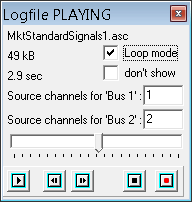
Click on the VCR-style 'Play' button [►] to start playing CAN messages from the file into the simulated CAN-bus. In fact, the messages read from the logfile are injected into the CAN-driver's low-level receive buffer.
Optionally, you can play the logfile over and over in 'Loop Mode'. This is
especially helpful if the file only covers a few seconds of recorded CAN
traffic.
Since May 2015, the relationship between CAN bus numbers in the Vector ASCII Logfile (*.asc)
and the CAN interface number in the simulierted device can be edited in the
Logfile Player's control window (see screenshot, "Source Channel for Bus 1" = 1",
"Source Channel for Bus 2" = 2).
If necessary, up to four source channels can be entered (separated by comma).
With these defaults, CAN messages recorded as 'channel number one' in the ASC file
will be treated as if being received from "CAN1" (in the simulated MKT-View), etc.
Reason for this: A customer had to simulate a CAN network where the first CAN interface (from the MKT-View's point of view)
had been recorded as channel number 8 (EIGHT) by some unknown tool.
During playback, the CAN-messages can also be displayed on the 'error page'
(set the option 'Show RX Frames' to see received CAN messages; in this case:
"received" means "played from the CAN logfile into the simulator").
Rejecting certain CAN messages in the Logfile Player
Certain CAN messages can be suppressed when playing back a CAN logfile into the simulator. For example, CAN frames with a certain message-ID may be contained in the recorded file, but would disturb the simulation and thus need to be suppressed. To achieve that, enter the hexadecimal message identifier(s) in the field labelled 'Reject (Rx,Tx,id)' on the logfile player panel. Multiple entries must be separated by comma. Furthermore, by adding 'Tx' in that field, all messages marked as 'Tx' (transmitted) in the logfile can be suppressed during playback, while 'Rx' can suppress playing all messages marked as 'Rx' (at least in "Vector ASCII" format). Example: Reject(Rx,Tx,id): 0x1CFECBFF, TxSuppresses all CAN messages with a (29-bit) identifier 0x1CFECBFF, and all frames marked as 'Tx' in the file (which means, we guessed, 'sent' from the recording device's point of view).
Automatic Stop of the CAN Logfile Player via script debugger
The built-in CAN logfile player is automatically stopped (paused) when the script hits a breakpoint in the script debugger. The CAN logfile player also remains paused when single-stepping through the script (F7 = single step).The player resumes ('continues to play') when the script is script is allowed to continue (F9 = run) at the position where it had been stopped before.
This avoids a backlash in the CAN-receive-buffer of the simulated device.
It also simplifies to debug own CAN-receive handlers (in the script), because after hitting a breakpoint (for example, in a CAN receive handler) you can easily switch to the 'Errors and Messages' tab, which will optionally show the most recent CAN message(s) 'sent' into the simulation by the CAN-Logfile-Player (at the bottom of the list, in chronological order).
CAN Message Generator / Simulator
The CAN message generator / simulator can be used to replace or simulate CAN messages
that you may need to test/develop your display application, when a suitable hardware (e.g. Motor Control Unit) is not available.
It can optionally 'inject' the simulated CAN frames into the display application (running in the device simulator),
but also generate 'real' CAN traffic in a very flexible (programmable) way.
Details about the CAN message generator / simulator are available in an extra file (CANSimulator_01.htm).
Wireshark-compatible Packet Capture option
Wireshark is a packet analyser which can 'spot' network-related problems, decode TCP/IP traffic, analyse timing, etc.
Once you got used to it, it does an amazing job to decode many kinds of Internet- and Ethernet-related protocols.
The packet capturing feature is integrated in the device firmware so you can examine packets received and sent by the programmable terminal.
(You could, of course, let Wireshark capture the packets itself, but in that case it can only 'see' the packets which arrived at the PC,
which is not necessarily the same as on the device 'at the other end of the cable'.)
The flag "received" or "sent", from the terminal's point of view, is also saved in the Wireshark-compatible capture file,
so it's easy to tell which of the captured packets has been received, and which of them has been sent.
Depending on the device configuration ("Main System Menu" .. "Diagnostics" .. "Ethernet Capture"),
the 'Packet Capture' buffer may contain received and transmitted Ethernet packets and/or CAN frames.
If you have no access to Wireshark, you can directly watch the Ethernet traffic on the terminal's own display.
Alternatively, the terminal can convert the captured data into simple HTML, which you can read and analyse
with any modern web browser. The screenshots below show the same captured Ethernet traffic in a browser (left) and in Wireshark (right).
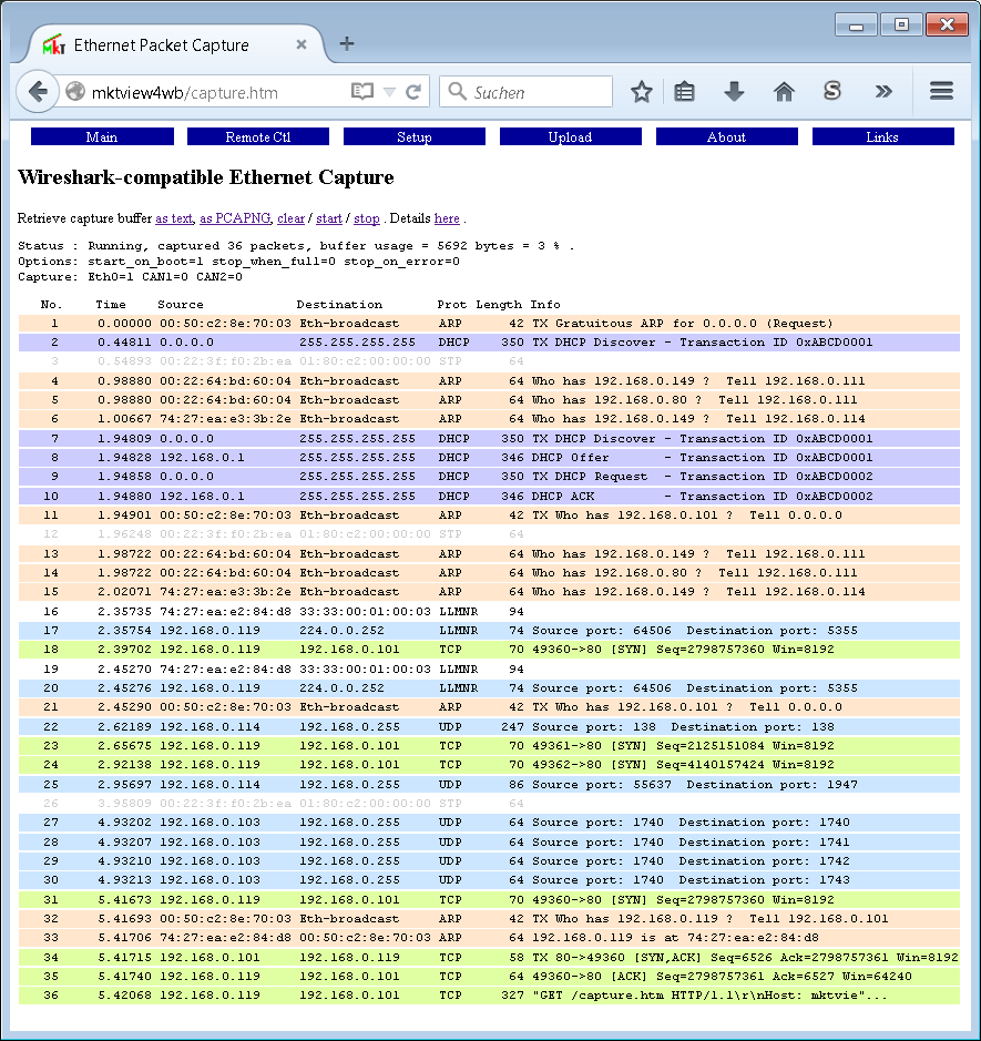 Browser-Screenshot with 'Ethernet Packet Capture'. Click into the image to magnify it. |
 'Real' Wireshark screenshot showing the same captured data. Click into the image to magnify it. Note that Wireshark identified a 'TCP Retransmission' to indicate a minor problem, which the built-in capture display (shown in the screenshot on the left) did not. |
Blue : Received frames (from the device's point of view),
Green: Transmitted frames (from the device's point of view).
Unlike the display in Wireshark, CAN message identifiers are not shown in the 'Info' field but in the column titled 'Source' (for received frames, blue) or 'Destination' (for frames transmitted by the device, green). 11-bit message identifiers are displayed with 3 hex digits, 29-bit IDs with 8 digits. For CAN, the 'Info' field only shows the data field (max. 8 bytes, hexadecimal without prefix). Example:
Packet Capture Status : Running, captured 5 packets .

    No.    Time    Source            Destination     Prot Length Info
    1     0.00000                   CAN1:0x07B        CAN    8  00 02 03 04 05 06 07 08
    2     0.13405 CAN1:0x000003FF                     CAN    8  05 44 4C 34 59 48 46 20
    3     0.43712                   CAN1:0x07B        CAN    8  01 02 03 04 05 06 07 08
    4     0.53385 CAN1:0x000003FF                     CAN    8  05 44 4C 34 59 48 46 20
    5     3.12532 192.168.0.206     192.168.0.234     TCP  117  TX "HTTP/1.0 200 OK\r\nContent-Type:"
The direct display as HTML lacks many of the features in Wireshark (recognized protocols, protocol errors, interactive inspection / decoding of thousands of different 'fields' in the TCP/IP data, ..). Thus, if possible, open the captured data in Wireshark (as shown in the right screenshot above).
User-friendly browsers can be configured to open Wireshark automatically when recognizing a PCAPNG file. The browser then downloads the capture buffer (capture.pcapng) and stores it as a PCAPNG file, launches Wireshark, which then loads and displays the captured frames in a matter of seconds.
Details about retrieving the wireshark-compatible capture file via integrated HTTP server can be found here (external link to the MKT documentation).
A few 'Wireshark Tricks':
- Looking for 'lost messages', for example in periodically sent CAN frames :
Define a filter like "frame.time_delta > 0.1", to show only frames following a (time-) gap of over 100 milliseconds (since the reception of the previous packet).
Because filtering for a certain CAN message ID is (or at least was) difficult in Wireshark, turn off the option 'any ID' via web browser, before starting the capture. Without the option 'any ID', the packet capture will only contain CAN messages with 'registered' message identifiers, for example messages that your application wants to receive via script, or CAN messages carrying signals defined via DBC-Import, and connected to display variables.
See also: Overview of Debugging aids, CAN functions
in the scripting language (added
2010-09), table of contents .
CANopen Configuration
Not for terminals with exclusive "CANdb" functionality like MKT-View (see Feature Matrix)
The Tab Sheet "CANopen" lets you define some additional CANopen-settings that do not belong to PDOs and SDOs. At the current time, the following elements of CANopen can be defined here:SYNC - Message
NMT (Network ManagementT a la CANopen)
SDO Client Channels (Button to switch to another tabsheet)
SDO Server Channels
PDO Channels
See also (concerning 'CANopen') : Programmable displays with "CANopen V4"
Configuration of the SYNC message
CANopen uses the SYNC-telegram to synchronize the transmission of PDOs. The UPT can transmit (produce) or receive (consume) this message if necessary. The behaviour of the UPT concerning SYNC may be defined on a special panel under "CANopen" configuration.NMT Configuration (CANopen network management)
CANopen uses the NMT-protocol to control all nodes in the CANopen network. NMT objects are used for executing NMT services. Through NMT services, nodes are initialized, started, monitored, resetted (reset?) or stopped. All nodes are regarded as NMT slaves. NMT requires that one device in the network fulfills the function of the NMT Master.You will find more information on NMT services in CANopen DS301 V4.0, chapter 9.2.6.1 (page 9-41).
The UPT can be either NMT-Master or NMT-Slave, but not both at the same time. The behaviour of the UPT concerning NMT may be defined on a special panel under "CANopen" configuration. At the present time, the UPT's built-in NMT functionality only supports minimum NMT bootup, no extended bootup !! (If you don't know what that is, you certainly don't need it). If the UPT acts as the NMT Master, it can send a "Start Remote Nodes"-broadcast after a programmable "Bootup-Time" (starting with turning on the UPTs power supply).
See also:
- CANopen object dictionary of the programmable terminal
- SDO access functions (only for terminals with CANopen V4)
- SDO error codes ("abort codes")
Data Transfer between the programming tool and the programmable device
Since development of a 'simple display terminal for the CAN bus' many years ago, the complexity of transfer options grew significantly.Most devices support the following transfer modes / methods between the programming tool and the programmable device :
- Transferring the application into the terminal ("Upload")
- Firmware-Update
- Remote control (for devices without a keyboard)
- Transferring other files (with the File Transfer Utility)
- Upload via Ethernet ( UDP ) using the programming tool
- Uploading files via web browser (TCP/IP; external link)
- Discovering MKT devices on Ethernet (using a DHCP server)
- Automatic display program update via FLASH memory card
For devices with FLASH memory card (like MKT-View) we strongly recommend
to transfer the application (*.upt or *.cvt) via memory card, because this
is much faster than transferring files via CAN or RS-232 .
See also: Accessing files via HTTP Server (external link)
Program Upload
After creating and debugging your UPT application as far as possible, you are ready to upload the application into the target (a UPT515, UPT167, CANdb-display terminals or similar).Newer devices (with a 'real' USB port, not just a USB/UART converter chip) can be identified automatically as a Virtual COM Port (see Transfer via USB / VCP). From a user's point of view, the operation is the same as described for RS-232 in the next chapter.
Transfer via CAN / CANopen or RS-232
Connect the terminal with the PC with an interface cable (and/or a suitable CAN bus adapter).Alternatively (if an RS-232 interface is availabe but no CAN), the serial port (often labelled "RS 232" on the adapter cable near the DSUB-9 connector) can be used to update the application or other files. But since the terminal's RS-232 port is often "occupied" by the application (via interpreter- or script-command), it must be temporarily be 'freed' before it can be used for transfer. To do this, enter the 'Main System Menu', enter submenu
Other Transfers ... ▶,
and select item Transfer via RS232 (SLAVE). In this context (file transfer via serial port), the SLAVE is the receiver, the MASTER would be the file sender. See details about transferring files over serial ports further below.
If the target is a terminal with CANdb functionality instead of CANopen, you must enable the program-transfer via CAN-bus:
- Enter the terminal's system menu (this is usually achieved by pressing the 2nd and 3rd function key simultaneously)
- Navigate to the menu item "Transfer via CAN = xx", press enter (or the rotary knob)
- Switch from "Transfer via CAN = OFF" to "Transfer via CAN = ON" (with the cursor keys or rotary knob)
- Press enter again to finish editing, and leave the system menu.
However, the above steps may be omitted if the 'Transfer Mode' is permanently enabled (i.e. set "Transfer via CAN = ON", then select "Save and Exit" in the setup). More details about the possible settings for 'Transfer via CAN' can be found in document #85115, titled System Menu and Setup.
Then, in the programming tool's main menu, select
- Transfer ...
-
Send Application to Terminal .
After a 'fresh' install, you may have to define how the programming tool shall establish the connection. To do this, select the following item in the main menu:
- Transfer ..
- Connection Parameters .... Medium .... CAN or Serial Port ("COM") or UDP/IP (Ethernet) .
If the programming tool cannot establish a communication, check the interface cables, termination resistors, communication parameters (baudrate etc) and try again. If still no success, check the programming tool's error page.
If you never sent a program to the terminal before, there can also be a problem with the installation of the CAN interface. Check our notes about the installation of a CAN interface, and carefully(!) read the documentation supplied with your CAN-interface.
To upload the application via CAN into terminals without CANopen protocol (like "MKT-View"), read this document too.
During the transfer, the programming tool shows its own software version (as 'recommended firmware' for the target), and the firmware version read from the remote device. Ideally, but are equal:
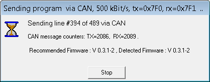
If only the revision or build number (3rd and 4th number) are different, new functions may possibly not exist in the target device, and an application which runs properly in the simulator (programming tool) may not work properly in the target device. An overview of software revisions, along with the latest additions, can be found here (on the MKT website).
Certain terminals like "MKT-View" can be loaded via asynchronous serial interface ("COM1" or "COM2"), or via memory card. See Feature Matrix. All terminals which have the load-via-card feature, have a unique way to update the display program automatically as described in a later chapter (-> "Autoload").
To transfer the application via serial port (formerly RS-232, for later devices
with USB and integrated FTDI USB<->UART adapter) you will need to know the
baudrate which is currently configured in the target device.
Note: There is no universal 'default value' for the serial port speed, because
some devices only support rather low speeds (especially those with 8- and 16-bit CPU);
furthermore the port's communication parameters could have been modified
via command in the display application itself.
The currently used baudrate is displayed on the device's screen after entering
'transfer mode via RS-232', for example:
Transfer mode active Receiving PROGRAM RS232/3964R: 19200 bit/sec |
To develop advanced applications (including scripts), the development cycle (modify-upload-test)
can be speeded up by transferring the application into the target's RAM instead of
the target's Flash memory. Details about script development, and how to test applications in the
target's RAM (i.e. "send to terminal without flashing"), are in the document about the
Script Language. Transfer 'without flashing'
can save about 10 to 60 seconds, depending on the Flash chips used in the target hardware.
Last not least, certain terminals (MKT-View II / III / IV) also support a general file transfer method which uses the YModem protocol. For example, you can load all kind of files (if they are small enough) into the terminal's internal FLASH memory, or copy files to the memory card via serial interface, CAN bus, or Ethernet / UDP/IP .
If there's a problem during (or shortly after) program transfer in the
remote device, the programming tool may display them in a message box like this:
![]()
Message box displayed when finishing a program transfer
with error text originating from the device firmware
(here: the line with "Couldn't save user settings")
- Couldn't save var-defs
The application's variable definitions couldn't be stored in the target system (at least not completely).
This may be caused by insufficient memory in the target, or a hardware problem (Flash memory).
- Couldn't save global event-defs
Global event definitions couldn't be stored.
Possible reasons: Similar as for other "Couldn't save .."-errors .
- Couldn't save the page-array
At least some of the user-defined display pages count't be stored in the target.
Possible reasons: Similar as above ...
- Couldn't save general settings
The general settings count't be stored in the target,
or are not compatible with / supported by the target system.
- Couldn't save user settings
The User Settings (settings also editable in the device) could not be stored permanently.
Since (in contrast to other parts of the configuration) these are usually not stored in Flash memory, but in an bytewise programmable EEPROM, the reason for this error may be a defective EEPROM chip. Please check the device's local 'Error History' (accessable via system menu). If there's an "EEPROM verify error at adr..", it's most likely a hardware problem that you cannot fix with a firmware update.
- Couldn't save an icon in Flash
At least one of the user-defined bitmap graphics couldn't be stored in the target's Flash memory. Since a part of the Flash memory is managed like a 'disk volume' (with flexible size), it may be possible to cure this problem as follows:
In the device's system menu, select 'Diagnostic' / 'Erase Flash (data)',
and then try again to load your application.
If nothing helps and you're in a hurry, ignore this problem- the application will run anyway, and missing icons will be omitted on the screen.
- Couldn't save Flash-shadow-RAM
This problem can only occurr on devices with 'large RAM but small (insufficient) Flash memory' for your application, or if there's a hardware fault. Similar as explained above, check the entries in the device's error history.
- Couldn't save PDO channel defs
CANopen-specific problem, related with Process Data Objects.
- Couldn't save SDO channel defs
CANopen-specific problem, related with Service Data Objects.
- Couldn't save CANopen-config
CANopen-specific problem, for other reasons (neither PDO nor SDO).
- Couldn't save Flash-shadow-RAM
Transfer / connection via USB and 'Virtual COM Port'
Modern devices like the MKT-View V (with USB and 'Virtual COM Port' implemented in software) identify themselves when connected to a USB host (e.g. a PC running windows) with a certain USB device descriptor. At least under Windows 7 / 8 / 10 / 11(?), such devices can be automatically detected by the programming tool.If such a device (e.g. "MKT-View V") is detected, but a different COM-Port is currently selected (on the tool's Settings tab), or no serial port is selected at all ('none'), then the tool automatically asks whether to switch to the automatically detected device. Example:
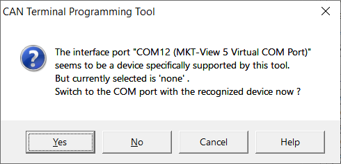
Prompt from the programming tool when detecting a 'supported device' when starting up.
Click 'Yes' to switch to the COM port with that device (identified by USB Product Name).
Transfer via USB and 'Media Transfer Protocol'
Modern devices like the MKT-View V (with USB and Media Transfer Protocol (MTP) besides 'Virtual COM Ports') can be 'programmed' via USB without the need for a special tool at all. At least with Windows, the "File Explorer" (formerly known as "Windows Explorer" or "File Manager"), these devices are recognized as a composite USB device with MTP, and listed under "This PC" ("Dieser PC"?). Better file managers like Total Commander also support MTP. The operation is similar as exchanging files with a smartphone or digital camera:- To upload (transfer from PC to MKT-View) a new display application, drag and drop your *.cvt from the local disk storage into the device shown as e.g. "MKT-View 5 MTP", into the storage medium labelled system.
- To read a screenshot from the display's framebuffer and store it as a bitmap file on your PC,
drag the file named screenshot.bmp from the storage medium labelled system,
and drop it into the a folder on your local disk. Then rename it to something meaningful
for the documentation of your application.
Alternative (if *.bmp files are associated with an image viewer / file converter like IrfanView):
Double-click on screenshot.bmp in file list for the MKT-View's system (storage medium, not a folder). Then (e.g. with IrfanView) store it as a *.png file, renamed to something meaningful.
- More names of files and 'storage media' inside the MKT-View's MTP file server are specified
here (in a separate document).
Transfer via Ethernet ( UDP )
To upload the display application (and possibly other files, using the already mentioned file transfer utility) via Ethernet / UDP, the programming tool must be informed about the IP address and the port number of the remote device.By default, devices like the MKT-View use DHCP to lease a 'dynamic' IP, and UDP port number 55556 for a variety of functions. This includes the CAN-via-UDP protocol, and a very simple file transfer protocol (both are based on UDP, not TCP/IP). If necessary, the target's IP adress can be detected as explained in another chapter.
To enter the IP address, and the port number, select
Transfer .. Connection Parameters .. Remote IP
(in the main menu), and enter the IP address, and (UDP-) port number of the device you want to connect. The syntax is <IP byte 1>.<IP byte 2>.<IP byte 3>.<IP byte 4> : <Port Number> .
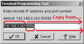
|
|
( Entering the remote address and port number in the programming tool.
IP address and port number taken from the remote device's network setup,
see screenshot on the right. Note: CAN-via-UDP set to SERVER . )
If the development PC has multiple network interfaces (for example, multiple Ethernet adapters), the local IP address of the development PC can be picked from a list:
In the programming tool's main menu, select
Transfer .. Connection Parameters .. Local IP
to open the dialog shown below. In the dialog, pick the IP address of your PC's Ethernet port. In a few cases, there may be multiple physical interface, which is why we need this selector. If the PC only has a single network adapter, the list contains only one item.
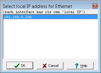
Furthermore, the IP address of the remote device must be entered to program or remotely control it.
If a static IP address is used (in the device, e.g. MKT-View), this is simple: Just read out the address in the devices 'Network Setup' (field 'IPaddr') and write it down (on paper) for future use.
If a dynamic IP address is used (leased from a DHCP server somewhere in the network), you can try to 'find' the device's momentary address via the tool's main menu, 'Transfer'..'Discover MKT devices on the Ethernet LAN', or (if that doesn't work for one of many possible reasons) read out address from the device's display as described below :
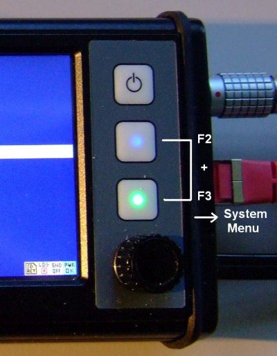
|
→ |
|
→ |
|
( Determining the IP address of an MKT-View when DHCP is in use.
Grayed entries in field 'IPaddr' mean 'leased address, not editable'.
In this case, the fields show the currently leased IP address. )
The UDP port number is actually shared with the CAN-via-UDP server (thus, the item 'CAN via UDP' must be set to SERVER).
Many devices made by MKT have this server for the CAN-via-UDP protocol built inside,
as crude replacement for a physical CAN interface installed on the PC.
(For developers, details about the protocol are in the documentation 'CAN-via-UDP').
But the presence of the CAN-via-UDP server in the firmware doesn't mean it is enabled !
Instead, it may be disabled through the device's Network Setup for security reasons.
A typical Network Setup (with the CAN-via-UDP server enabled) looks like
this:
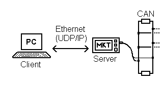
|
|
typical CAN-via-UDP client/server configuration and Network
Setup in an MKT-View III
When initiating a transfer via Ethernet (UDP/IP), some paranoid 'Internet Security Suite', or the windows firewall, may block the transfer. In some cases, such a security software will inform you that it has blocked the access ("blabla is trying to act as an internet server" which is nonsense, anyways..), or will ask you for permission:
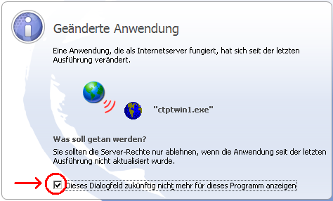
Other Examples :
- "Eine Anwendung, die als Internetserver fungiert, hat sich seit der letzten Ausführung verändert." (after program updates)
- "ctptwin1.exe (or uptwin2.exe) is trying to access the internet / act as a server / etc" .
- ... (feedback, please)
Kindly allow the programming tool to access the "internet" (in fact, it doesn't access the internet, it only tries to establish a connection through the local network using UDP).
Details about the Network Setup can be found in
document #85115, "System
Setup" (PDF, for users / operators) .
The protocol (on top of UDP/IP) is described
in document #85140, "CAN via
UDP" (PDF, for developers) .
How to use transfer other files via Ethernet is described in the
'File Transfer Utility / Transfer
via Ethernet' (HTML, part of the help system) .
See also:
file transfer via web browser (HTTP; external link),
Discovering MKT devices on Ethernet (using a DHCP server) .
Discovering MKT devices on Ethernet (via DHCP or OpenABK-'Discovery')
In most cases you will know the device's IP address or host name; thus there's no need to 'discover' the device as explained below. Simply enter the device's IP address or hostname (default: UPT) in the address bar of your favourite web browser, and continue here . The same applies to selecting the target device before uploading an application via Ethernet.To 'discover' Ethernet devices by MKT in your local area network, select Transfer .. Discover MKT devices in the Ethernet LAN. This opens a dialog window, which guides you through the steps shown below. If all goes well, the program will detect the MKT device (identified by its MAC address), and show the device's current IP address (by listening to the DHCP traffic, or via openABK-'Discovery'-protocol).
Step 1:
DHCP Server / OpenABK-'Discovery'
This function may be used to 'discover' an MKT-Device in the local network, without knowing the IP address of the remote device. In the next step, this program will try to find an MKT-Device, using the OpenABK-'Discovery'- and DHCP protocol. Depending on the windows version, you may have to allow this in the firewall. Click 'OK' to allow this program to act as a DHCP-SERVER and as an openABK-CLIENT temporarily. |
Step 2 (old, without openABK):
Waiting for reception of DHCP packets
The built-in DHCP server has been started, and is now waiting for reception of a 'DHCP-Discover' packet from a display made by MKT Systemtechnik. THE MKT DEVICE MUST NOW BE RE-STARTED FOR THIS PURPOSE. Please make sure the devices is configured for DHCP, and connect it to the PC via Ethernet cable. Then turn on the device. Shortly after turning the device on, the Ethernet activity LED should light up, the reception of a 'DHCP-Discover'-Packet should be detected here. Click on 'CANCEL', if you want to abort the connection set-up. Rx:DHCP-Request cip=192.168.0.106 mac=00:21:00:DD:19:A1 (etc) |
Step 3:
MKT device detected - connect it via Browser ?
A DHCP server has received a 'DHCP-Discover'-Paket from an MKT device,
and assigned IP-address

     192.168.0.101

to that device.

Click 'Connect' to establish a connection to that device via web browser,
   or 'OK' to select this device as the current target system,
   or 'CANCEL', if you want to abort the connection set-up.
|
At the last step, click 'Connect' to establish a connection between PC and the programmable device
via web browser.
You can now use your web browser to upload display applications
(*.upt or *.cvt) into the device, transfer other files, update the device firmware, remotely control it,
get a screenshot of the current display (via copy-and-paste), dump the values of all display variables,
examine the trace history, etc.
Example:
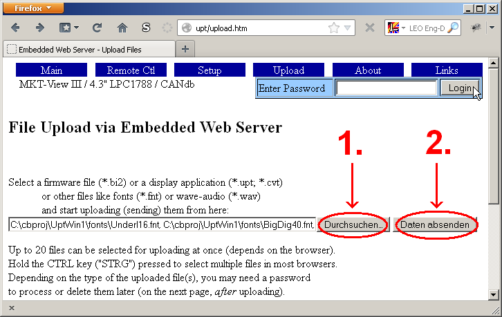
More details about the device's integrated web server are
here (external link).
Alternatively (without a web browser), the UPT programming tool can use the new detected IP address
to upload the application (or other files) as explained in the
previous chapter, using UDP (not TCP/IP).
To do this, don't click on Connect in step 3 but on 'OK'. This will copy the
new IP address into the programming tool's configuration.
The (UDP-)port number will be set back to the default value (55556).
After this, if the target's CAN-via-UDP server is enabled, you can transfer your display application
quickly into the target by selecting Transfer ... Send applikation to terminal.
OpenABK 'Discovery' Protocol
Besides listening to DHCP as explained in the previous chapter, MKT devices can also be detected in the local network (Ethernet LAN) via the openABK 'Discovery' protocol.Advantages: Doesn't rely on intercepting DHCP traffic, and thus also finds devices
with a static IP address.
Also, it's not necessary to turn the device off and on again (to force DHCP transmission) anymore.
Disadvantage: Only discovers devices with firmware compiled 2015-11-26 or later,
because older devices don't support the OpenABK-'Discovery'-protocol.
Note: Some MKT-Views (e.g. MKT-View III) support the OpenABK-Discovery-protocol, but they don't necessarily contain a fully-fledged OpenABK-HTTP-client or -server !
Devices which only support the discovery protocol will respond with "Key":"UPT" rather than "Key":"AbkServer" in their JSON-response for a 'discovery'-request (UDP broadcast).
This prevents problems with other OpenABK-clients in the network, which try to find 'their' expected OpenABK-server.
Devices 'discovered' this way are listed with their IP-address and 'name' (MKT: host name) in the programming tool:
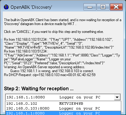
(Screenshort with devices discovered after 'Transfer'..'Discover MKT- and OpenABK devices in the local network'.
Various devices have been found in the local network,
amongst them an MKT-View (4) with host name "MKTVIEW4WB"
and an Open-ABK-'Test'-Server reporting a wrong IP address in the response )
(Years later, in 2021, openABK appeared to be a 'dead horse', and future development is unlikely.
Only the 'discovery' protocol is here to stay, since it has been implemented in almost every device by MKT with an Ethernet interface, and the programming tool relies on it.)
The protocol specification could be downloaded from openABK.org.
For english readers: 'openABK' = 'offenes Anzeige- und Bedienkonzept' = an 'open' protocol for the interaction between a 'display' and a 'logger', using TCP/IP, HTTP, and various web services.
Automatic display program update via FLASH memory card
When powering on, the firmware inside the terminal checks if a FLASH memory card is inserted, and if a special file is located in the root directory. The name of that file is:- "autoload.cvt" for all terminals without CANopen (parametrized through CANdb, like the original MKT-View)
- "autoload.upt" for all terminals with CANopen-support (like the "UPT2"-family of devices)
Encrypting the application with a user defined password
In a "sensitive" environment, you may want to protect your display application (in the form of a *.cvt file) against being 'analysed' by others, but still be able to distribute it to a customer via email, on a memory card, or already loaded into the device when shipped. To just run the application, your customer does not need to know the password.To set (or clear) a password for your display application, ...
- Open the programming tool's File menu,
- Select 'Password Protection' .. 'Enable password'
(if the currently loaded file is already protected,
the menu item will show 'Disable password' instead) - In the dialog that opens now, enter the same password twice
- Optionally provide a 'Hint' to remember the password later.
(this helps a lot to remember which password to use,
if you use a lot of different passwords in your *.cvt files) - Click 'OK', and don't forget to save the application as a file
if you want to keep the file encrypted on your local harddisk storage.
- Alternatively, you can encrypt the 'loaded' file immediately before sending it into
the target (e.g. MKT-View) via CAN, without touching the (non-encrypted)
file stored on your local PC.
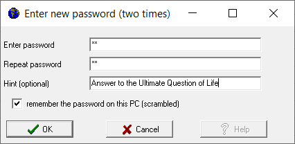
Entering a password to encrypt the display application, in the Programming Tool.
- Even when "encrypted", the *.cvt file still remains valid ASCII text.
Letters remain letters, numbers remain numbers, spaces remain spaces, and certain characters (including "carriage return" and "new line") are not replaced / encrypted / garbled.
The first few lines of text in the file are not encrypted ("garbled") at all, so even if you lost the password, you can still read the name of the original file, timestamp, and the self-defined 'Description', as in the example of an encrypted (password-protected) file:
; File: C:\cbproj\UptWin1\programs\password_encryption_test.cvt ; Saved: 2026-05-07 11:14:36 ; Type: program file for user programmable terminal ; Producer: programming tool compiled Apr 8 2026 Description="'Test for a password-protected / encrypted display application" Encryption=****** (some numeric hash value, calculated from something...) PuhQxrh8="Bcckmm ld slw Azvkauzn Ulupdokv tm Ogsx" (that's the first ENCRYPTED line of text in the file) Pygzqqce8="91" (next line, still recognizeable as a key=value pair, but both are garbled) ; ------- Urpyywhi lvybrtrcy --------------------- t nmirsrsv_dofovvt=XGJUGPS_5 t yliefnti_mxhhxcf=IHDu7 ..... - When loaded into a programmable display (e.g. MKT-View), the firmware can "run" the application without having to manually enter the password. But even after 'reading it back' from the device, the application is still encrypted / password-protected, so without knowing the password, it's impossible to view / understand / edit / extend the application, including its display page definitions, variables, CAN signal database, script, etc !
- Even MKT Systemtechnik cannot restore a "forgotten" password from an encrypted display application.
So store your password(s) in a safe place, along with the optional 'Hint'. You've been advised.
- The encryption remains intact regardless of how you transfer the application -
either as a *.cvt file on a memory card, or via CAN, via RS-232, via USB / Virtual COM Port, via USB / Media Transfer Protocol, or whatever !
Firmware Update
When sending your terminal application into the terminal, the programming tool may tell you that the terminal's firmware is too old. In this case, a firmware update in the terminal is necessary to maintain the compatibility between the programming tool and the terminal.A guide how to update the terminal's firmware is in the same directory in the file fwupdate.htm . In that document you will also find the password which must be entered in the programming tool to upload the firmware via serial port or CAN-bus.
Before updating the terminal's firmware, also read the firmware release notes carefully before proceeding. It may describe some hardware-specific limitations which are not mentioned in the programming tool's manual !
Then, in the tool's "Transfer" menu, and select "Update FIRMWARE via serial port". The tool will then prompt you for the password which you found in the above document.
Notes:
- The firmware in MKT's UPT515 can only be updated via CAN-Bus, because this device has no serial port. You need a special program (written by MKT) in this case. For more info, see fwupdate.htm.
- Never interrupt a firmware update, if it's already in progress ! During transfer, do not start any other programs to minimize the risk of a PC crash. If such an accident happens, or someone rips the cables off, you must activate the terminal's bootloader manually be pressing the 1st and 3rd function key while turning the terminal's power on, and repeat the firmware update.
- (Not translated into english yet ... use your imagination ... )
Für Geräte mit ARM-CPU (z.B. MKT-View II, seit 11/2008) wird zur Ablage der Firmware nicht mehr das HEX-Format ("Intel Hex") verwendet, sondern ein platzsparenderes, segmentiertes Binärformat mit der Dateinamenserweiterung "BI2" . Achten Sie darauf, dass Sie beim Laden der Firmware für diese Geräte in der Dateiauswahlbox den Dateityp von "HEX Files" auf "SEGMENTED Binary Files (*.BI2)" ändern, andernfalls werden Sie die passende Datei nicht finden. -
For newer devices with Cortex CPU, 'sufficiently large RAM, and an integrated web server
the firmware can be uploaded into the device's RAMDISK via HTTP .
Details are in the desciption of the embedded HTTP server .
See also:
Firmware Compilation Date, readme.txt in the "firmware" folder, Firmware Release Notes, file transfer via web browser (HTTP; external link) .
The PC's CAN interface
To communicate via CAN-bus, the UPT programming tool requires a CAN-interface for the PC. This interface will usually be connected to the USB port, or (a long time ago) on the parallel port (like "CAN-dongle" by PEAK or "CAN-PCC" by ESD).Before installing the CAN-Hardware in your PC, you must read the instructions of the CAN interface's manufacturer ! MKT will not be responsible for any damages.
The following interfaces can be used in the UPT programming tool:
-
PCAN-Dongle by PEAK
The PCAN dongle is a simple interface for the parallel port. Since August 2001, using one of Peak's CAN software drivers is recommended, preferrably the "PCAN Driver V2".
-
NTCAN by ESD
The NTCAN API supports several CAN interfaces, like interfaces for the parallel port, ISA- and PCI-slot.
-
KVASER CANLIB
A universal and very robust driver Kvaser AB, supporting all (?) of Kvaser's recent CAN bus interfaces for the PC.
Since 2019, the programming tools by MKT also support CAN FD with suitable interfaces by Kvaser. In the programming tool, the 'fast' bitrate for CAN FD must be configured in the CAN Bus Parameters dialog to match the current device settings.
-
VECTOR XL Driver
Last tested with 'CANcase / VN1610' on a Windows 7 PC, where the relation between 'Channel' and physical interface required a bit of trial-and-error (until arriving at the correct 'Channel Name').
See hints about the Vector CAN Hardware here.
To 'upload' (send) configurations from PC into the programmable device, we generally recommend to use other interfaces (which are much easier to install and use on a windows PC than CAN), for example a serial port (RS-232 or virtual COM port) or the Ethernet interface as explained in the next chapters.
Configuration of the CAN interface for program transfer
For a successful program transfer via CAN, the communication parameters must be 'sufficiently compatible' between programing tool (on one end of the CAN cable) and the programmable device (on the other end of the cable). After loading a new configuration (e.g. from a *.cvt file), the configuration of the first CAN interface may differ significantly from the current settings of the PC's CAN interface. The programming tool would indicate auch a problem on the 'Settings' tab, under 'Programming Tool Settings'.- Note
- If the 'Programming Tool Settings' (concerning program transfer via CAN)
are not sufficiently compatible with the settings for the to-be-programmed
device's first CAN interface ("CAN1"), the programming tool will
mark those dialog elements with a red background.
But the programming tool will never try to 'automatically' correct any CAN-related setting !
In the screenshot below, there's a conflict because the PC's CAN interface was currently configured for 'classic CAN' not CAN FD, while the to-be-programmed device (MKT-View V with CAN FD) was configured for a "fast data phase" ("FD") with 4000 kBit/second.
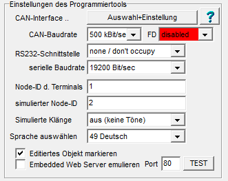
If the PC is equipped with a multi-channel CAN interface, the second channel can be used to simulate port "CAN 2" of a multi-channel device (e.g. MKT-View III/IV/V). In contrast to "CAN 1", "CAN 2" is not intended for program transfer and thus has no extra configuration in the programming tool. Instead, "CAN 2" always uses the parameters entered in the CAN Bus Parameters dialog under 'CAN 2'.
See also : Dialog to configure up to four (?) CAN interfaces in the to-be-programmed device.
USB-to-Serial Port interfaces (Virtual COM Ports)
Certain terminals (like "CVT-MIL 320") have an integrated USB-to-Serial-Port adapter, sometimes called Virtual COM Port. Recent Windows versions (at least XP) will automatically detect this type of USB adapter automatically when you plug in the device for the first time, and install a bunch of drivers (by FTDI, FT232R, VCP, etc).
If Windows fails to recognize the USB device, try to find the right
VCP driver for your operating system on the
FTDI website, and install
it yourself. Please respect the fact that we (MKT Systemtechnik) were unable
to test the FTDI VCP drivers on all of the fourteen different windows
versions which supported the FTDI chip (FT232R) in January 2010.
If you run into trouble with the USB drivers, it may help to plug the device into a different USB connector (your PC will definitely have more than one). Sometimes windows seems to lose track of the USB drivers installed on the system, and refuses to recognize the device with a message like this:
(Did you really expect to fix an USB driver bug by clicking on this message ... ?)
- Important note on USB, which has always been a nuisance for developers:
-
Always connect the programmable terminal to the same USB plug on your PC.
Otherwise, Windows will always select a NEW COM PORT NUMBER which is very, very annoying.
If, for example, Windows decided to use "COM10" yesterday, but "COM11" for the same device today, you will find something like the following in the combo list of serial ports:
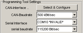
Furthermore, connect the terminal's "USB port" (which is in fact a virtual COM port) to the PC before starting the programming tool.
If the connection between the PC (programming tool) and the programmable device (terminal) uses USB and a Virtual COM Port, the 'serial' baudrate can be set to unusually high values (like 230400 or 460800 bit/second) on the 'programming tool settings' tab. In 2010, most new devices with ARM-CPU and USB/VCP had an automatic baudrate detector function built inside the firmware, so in those cases, the file transfer utility can use this higher baudrate even though the default baudrate (in the terminal) is only 19200 bit/second, or the display application has switched to a different baudrate via interpreter command .
See also:
The UPT's internal System Menu
Most programmable displays by MKT have a built-in system menu that you may enter with a special combination of keys (for example, F2 + F3 pressed simultaneously, or whatever you defined as "key combination" under general options ).
|
In devices which only have a touchscreen (but no "real" keyboard), the system menu can be invoked via the touchscreen gesture "rectangular U", as shown in the photo below:
|
|
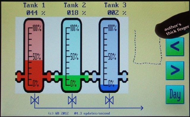
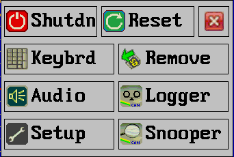
Details about the system menu are in the printable PDF, see the link to document #85115 at the end of this chapter.
In many devices, the system menu can also be operated via
remote control, for example through the RS-232
interface and a terminal program, or through the Ethernet port using TCP/IP
and TELNET. In those cases, send CTRL-S (STRG-S) from the remote terminal
as a replacement for simultaneously pressing F2+F3.
Here is one example of a system menu (snapshot taken from old UPT515 firmware,
it may look totally different on your hardware but the basic principle is
the same):
The basic operation of this system menu (and sub-menus) is as follows:
- press the special key-combination to enter the system menu (if not disabled by the general options, otherwise use the trick described here )
- use the Cursor UP / DOWN keys to scroll the black selection bar to the desired menu item
- press ENTER to edit the value of a menu item or to "jump" into that menu
- press ESCAPE to return from a menu
- use the menu item "Save & Exit" after modifying values that shall be saved permanently (like, for example, the contrast value for the LC-display)
Where applicable, you will find menu items to initiate a program upload manually (in the Mobile CAN Terminal, where the SDO server must be activated expecially for program upload).
Display-, Audio-, CAN-Bus-, and other items in the System Setup
Some important parameters which have to be set in the UPT's internal System/Setup menu are:- Display setup, hardware dependent, possibly
with LCD-contrast adjustment, backlight control,
clockwise or counterclockwise rotation for 'Portrait' mode (depending on how the device is mounted), touchscreen gesture options, etc; - Audio setup, also hardware dependent, with settings like touchscreen click volume, microphone gain (where applicable), speaker output volume, etc;
- Date and Time setting, if a battery-buffered real time clock is supported;
- CAN setup: Important for the communication between UPT and programming tool.
- Module/Node-ID (very important for the communication between UPT and programming tool)
- Network Setup : see next chapter .
- other hardware dependent features like CAN-Transmit-Enable etc
- Enter an unlock code to activate certain, 'special' features
- Diagnostic functions like bootloader invocation, recall default settings, error- and trace history display, manual 'browsing' of display pages, memory usage ("Storage Directory"), etc.
Note: CAN-Baudrate and Node-ID must be equal in the UPT's Setup menu
and in the programming tool. Otherwise you cannot upload UPT files from the
programming tool into the UPT (see chapter general
settings ).
Caution: The terminal application may have to run with a CAN baudrate
which is *not* supported by the PC's CAN interface (10 kBit/sec for example).
For that reason there is an extra definition for the CAN-baudrate for
the application in the programming tool on panel "Terminal Settings".
These two different places to set the CAN baudrate caused some confusion
in the past - more on that in the chapter about the tool's
Terminal Settings
panel (remember this when the programming tool cannot communicate with the
terminal, because you changed the CAN baudrate somewhere !).
On certain terminals, there is a menu item called User Settings where you can..
- Show and modify the "operational" baudrates for two CAN interfaces. These CAN baudrates are part of the application, not part of the terminal's system settings. The "User Settings" take effect when the terminal loads and initializes the application. If there is no application loaded, the terminal uses the CAN baudrate from its "system" menu. If the CAN-baudrate in the terminal is different from the CAN-baudrate used by the programming tool, you may get into trouble... see 'Download troubleshooting' in that case !
- If you need a CAN-baudrate which you do NOT find in the list of supported baudrates, you can -alternatively- define the value written into the CAN controller's BTR (bit timing register) directly in hexadecimal form. Caution: this option only exists in a few terminals (like MKT-View "Plus"), and we highly recommend NOT to use this feature because you will have to calculate the BTR-value yourself. More info on that subject can be found in this extra document (only available in english language).
- Edit the values of the non-volatile numeric array (located in EEPROM, can be accessed through the UPT interpreter)
In devices with a sufficiently large code memory, the following 'diagnostic' functions can be invoked through the system menu / submenu "Diagnostics":
- Inquire version info, compilation date, and status of unlockable features
- Invoke the bootloader (for a firmware update)
- Restore the "BIOS" default settings (baudrates, node identifiers, etc)
- Show the error- and/or trace- history (for devices with script support)
- Browse the programmable display pages:
After switching to a different page (here: via cursor keys or rotary button), the current page number and -name as briefly displayed. Press Escape or F3 to return to the 'Diagnostic' menu. - List all display variables (including their current values)
- List all objects currently stored in Flash memory ("Storage Directory")
- Erase all Flash memory ranges with data and application ("declassify" before shipping)
- Show extended CAN / CAN FD bit timing parameters
Devices with built-in CAN logger (e.g. "MKT-View") also have a built-in CAN bus monitor (CAN Snooper), which can also be invoked through the system menu.
Some of the functions in the system menu can also be invoked directly from the user application with an interpreter command , for example to adjust the display contrast or set the battery-buffered clock (if present).
If the device has neither a keyboard, nor a rotary encoder knob, nor a touchscreen, the system menu must be invoked via Remote Control (requires a special terminal program).
Since 2011-07-12, a few (display-related) setting in the system menu can optionally be overwritten when downloading a configuration (*.cvt or *.upt). See optional display setup for details.
More information about the terminal's "System Menu" can be found in this printable document (PDF #85115) .
Alternatively, devices with Ethernet (and TCP/IP) connection can be configured via
web interface (HTTP) .
Network Setup (in the system menu, only for devices with Ethernet / TCP/IP)
For devices with Ethernet port and TCP/IP, the Main System Menu contains an item labelled Network Setup.The network setup must be used to set the local (and static) IP address of the device, and other parameters relevant for TCP/IP (and, sometimes, UDP).
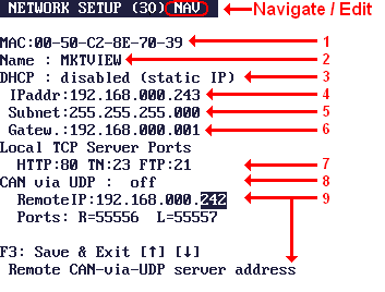
- (1) The device's Ethernet MAC address .
- (2) The device's name (hostname) in the local network .
- You can access the device by entering this name in your web browser,
which may be easier than entering the IP address - especially in combination with DHCP.
The default name is "upt" (short for User Programmable Terminal), but you may want to modify the name. You must change the name if you have multiple "upt"s or MKT-Views in your local network. - (3) Configuration of DHCP (static or dynamic IP address)
- If a dynamic IP shall be used, there must be a DHCP server somewhere in the network, and the following fields (4..6) are meaningless.
A fixed IP may be easier to use, especially when communicating with other embedded devices which don't support DHCP. - (4) The device's own (local) IP address .
- This is the static IP, which is saved in a configuration EEPROM. Only has an effect if DHCP is disabled (see item 3).
- (5) Subnet mask
- Like the static IP (4), this parameter only has an effect DHCP is disabled.
- (6) Default Gateway Address
- Like the static IP (4), this parameter only has an effect DHCP is disabled.
- (7) Local TCP Server ports:
- HTTP: Integrated HTTP server aka "web server" (default port: 80), Telnet (default port: 23), and FTP (not functionable yet, default: 21)
- (8) CAN-via-UDP mode : Possible settings are "off", "Client", or "Server".
- Note that unlike some PC software, the terminal can be either client or server, but not both at the same time.
- (9) CAN-via-UDP parameters :
-
IP address of a remote CAN-via-UDP server (used if the device acts as a client),
and local port number if the device acts as a CAN-via-UDP server itself.
Note: If you are not familiar with the basics of TCP/IP, follow the external links (which mostly lead to Wikipedia). Furthermore, read a good textbook on network basics !
Pressing the enter key (or, if no such key exists, the rotary encoder button) to switch between 'Navigate' (i.e. move the selection) and 'Edit' (i.e. modify the selected parameter). A short note about the currently selected parameter is visible in the bottom line.
Details about the network setup can be found in document #85115 ("System Menu and Setup").
Alternatively, the network setup can be modified via web interface as described
here .
See also: Suppressing popup messages when launching certain services (e.g. DHCP, CAN-via-UDP, WLAN)
Wireless LAN Setup (for devices with WLAN/'Wi-Fi' instead of Ethernet, e.g. MKT-View V)
Power-on/off behaviour of the device, e.g. Wake-up via CAN
Note: The features described in this sub-chapter only apply to devices with a buit-in 'standby controller', as used in e.g. the MKT-View II / III / IV / V .Other devices may lack support of e.g. wake-up on CAN bus activity.
Per default, devices like the MKT-View are turned on by pressing the 'power'-button (often combined with the F1 key), and turned off via long press of the 'power'-button or 'programmatically' via script (system.shutdown.
The device's behaviour during the 'off' state (where only the 'standby controller' remains alive, consuming fractions of a milliampere) can be configured in the device's System Setup as follows:
- In the 'Main system menu', select 'System Setup / UNLOCK'
- In the 'Setup Menu', scroll down to the item 'WakeupSource'.
- Press ENTER (or the rotary encoder knob) to switch from 'Navigate' to 'Edit'
- Using the up/down key (or rotary encoder), select one of the items explained further below.
|
(Configuring the device's 'wake-up' behaviour)
- Key (only)
- The device (MKT-View) can only be turned on via (power-) key.
If will not automatically turn itself on when the supply voltage ("Vin") returns.
- Key, Vin
- The device (MKT-View) can be turned on via key (after manually being turned off),
and it will automatically start when there is a low-to-high transision at "Vin" (supply voltage).
- Key, Vin, CAN
- Similar as above. In addition, the device will automatically start when there is
activity on the first physical CAN bus interface.
- Key, DIN, CAN
- Similar as above. In addition, the device can be started via onboard 'digital input'
(DIN).
Please consult the hardware manual for details and specifications.
- Key, Vin, DIN, CAN
- Combination of all the above (power-on via key, rising supply voltage, digital input, CAN-bus-activity).
- Key, CAN
- Power-on only via key or CAN-bus activity. Rising edges on VIN or DIN are ignored.
- Vin, CAN / Vin, DigIN / Vin (only) / CAN (only)
- Rarely used combinations that don't allow the human operator to turn the device on by himself.
These were requested by a 'good customer' many years ago, and are possibly not available on newer devices anymore.
Unlocking 'special' features
Certain devices are equipped with certain 'special features', which must be unlocked (..for a moderate fee..) before you can use them, for example the built-in CAN-logger, 'snooper' (CAN bus monitor), GPS decoder, audio recorder, certain CAN transmissions, extended functions in the script language, and maybe more.Details about unlocking such features have been moved into an extra document (Unlocking 'special' features).
Remote Control (for the programmable terminal's system menu)
Some "display terminals" by MKT Systemtechnik have neither a keyboard, nor a touchscreen, nor a rotary encoder button. To configure and control them (especially operate the terminal's system menu), a crude and simple remote control function was added in the firmware of such devices.Devices with integrated web server (like MKT-View II, MKT-View III) can also be configured and supervised via embedded web server. Depending on your network settings, a device may be accessable in a web browser using a simple address (pseudo-URL) like UPT (UPT=default host name for all User Programmable Terminals).
Details about how to operate the system menu via remote control (or web browser) can be found in the document titled Remote Control for programmable terminals.
Return to the table of contents
Storage Directory (in the 'System Menu' under 'Diagnostics')
For normal applications, you don't need to care about the memory sizes consumed by your application in the target's flash. So skip this chapter, unless you are running out of memory, or plan to run an application originally written for a device with plenty of Flash memory on a device with tougher memory constraints.The 'Storage Directory' is a scrollable tabular display with the following columns:
- Nr
- Item number. Scroll down to see higher numbers, since the text screen is too small
to show the twenty items that existed in complex devices (12/2020).
- Type
- This column shows the type of an item. In most cases, there is only one entry per type,
but this may vary (for example on complex systems with "small but fast" and "large but slow" memory
areas, or chips with different bus interface (serial, I2C, SPI, or with an 8 / 16 / 32 bit data bus).
So far (december 2020), the following items existed:
- GENS
- General settings. This is a fixed-size struct, but the size may depend on the target device and CPU.
- SDOs
- Service Data Objects (for CANopen). This is a fixed-size array, but it may be missing in devices without CANopen.
- PDOs
- Process Data Objects (for CANopen)
- VARI
- display-variable definitions. This is a variable-sized array of structs.
- G_EV
- global event definitions
- CANO
- CANopen configuration (besides SDOs and PDOs)
- user
- optional user settings, or special customized "user specific" objects
- CdbH
- CAN Database Import History (the list of files imported into the application)
- CdbS
- CAN Database Signal Definitions (as far as required for the application)
- ufnt
- User-defined fonts (imported into the application)
- ufre
- User-defined font references (list of files with user-defined fonts)
- FREF
- other File References ("files used by the application", as far as the programming tool could see)
- FLEX
- other objects in the 'flexible' (dynamically allocated) part of the Flash storage
- STRG
- zero-terminated string literals (from different objects, but not the script sourcecode)
- ICON
- Icons (bitmap graphics imported by the programming tool)
- PAGE
- Display pages
- TEXT
- text array
- SCRI
- script sourcecode
- DYNA
- other 'dynamically allocated' objects in Flash memory, most of them allocated after downloading the application into the programmable device.
- Count
- Number of objects of a certain type, stored in a single memory block.
- kByte
- Size of the occupied memory block in kByte (1024 byte units).
- FirstAddr
- Start address of the memory block from the CPU's point of view.
Only displayed here for debugging and software development.
Memory addresses are extremely target specific. "Low" addresses are often
the CPU's internal (and very fast) Flash memory.
- LastAddr
- Address of the last entry of a certain type. Only meaningful for array-like items.
Due to the sequence of items allocated due to a program transfer, address ranges may seem to overlap. This is caused by the fact that some items (likes strings) may have to be allocated while importing other items (like display pages, which contain a lot of variable-sized strings).
Nr Type Count kByte FirstAddr LastAddr 01 GENS 1 1 0x29873BA4 0x29873BA4 02 SDOs 0 0 0x00000000 0x00000000 03 PDOs 0 0 0x00000000 0x00000000 04 VARI 40 7 0x2986CDBC 0x2986E6B8 05 G_EV 31 22 0x2986E75C 0x298738EC 06 CANO 0 0 0x00000000 0x00000000 07 user 0 0 0x00000000 0x00000000 08 CdbH 1 2 0x29873EF4 0x29873EF4 09 CdbS 21 2 0x2986C034 0x2986C82C 10 ufnt 0 0 0x00000000 0x00000000 11 ufre 1 1 0x29873EA8 0x29873EA8 12 FREF 0 0 0x00000000 0x00000000 13 FLEX 0 0 0x00000000 0x00000000 14 STRG 242 9 0x29840198 0x2986CD94 15 ICON 99 143 0x29848828 0x2986B680 16 PAGE 20 27 0x29840000 0x2986C89C 17 TEXT 1 1 0x29848810 0x29848810 18 SCRI 0 0 0x00000000 0x00000000 19 DYNA 0 0 0x00000000 0x00000000 Entries=19 used: 215; unused: 814 kByte |
After the table (with the items listed above), the 'Storage Directory' shows the number of entries, and the remaining unused Flash memory size in kByte.
The latter is the best indication about how much 'larger' your application may grow (by adding more display pages, more script sourcecode, importing more icons, etc) before running out of Flash memory.
The list of items (and their sizes) can help you to decide what to remove from your application to free enough memory for running the application on a different (smaller) device.
See also: Determining the Flash memory usage in the programming tool.
Advanced Information
This chapter provides some information about the internal functions of the User Programmable Terminal.- Interpreter Commands
- CANopen-Objects inside the Terminal
- SDO error codes
- Troubleshooting and frequently asked questions
- Glossary
An excerpt from the programming tool's revision history can be found
here.
An excerpt from the device firmware revision history is
here, and detailed firmware release notes are here.
Troubleshooting and FAQs
This chapter contains a collection of (more or less) "common" problems and their possible solution. See also: FAQ (frequently asked questions).- Issue: Immediately after power-on,
an MKT-View (II,III,IV,V) sends Morse code through the internal 'beeper'
but nothing appears on the screen.
- Reason: This 'Morse' output is a left-over from the firmware development phase.
It an ARM-Cortex processor 'crashes' for one of dozens of possible reasons,
it gets stuck in an 'exception' handler. If this happens before the CPU had
the chance to initialize the LC Display (for example, due to problems with
the SDRAM or Flash memory), sending out an error message in Morse code
through the internal speaker (aka 'buzzer' or 'beeper') was the only chance
to give the developer (a Ham Radio operator) a chance to "hear what had gone wrong",
because without functional SDRAM, the CPU cannot drive the LCD at all.
Fix (1): If you hear those Morse code 'dots and dashes', turn the device off, let it 'cool down' for a minute, and turn it on again. In most cases, if the crash (exception) was caused by an EMC problem, or by a too-slowly-rising supply voltage (which broke down again as soon as the CPU started "drawing current"), the 'cold start' will work properly.
If the problem occurrs more than once, and cannot be cured by a 'cold start' or a firmware update plus re-loading of the user application, return the device to the manufacturer for inspection. Leave a note for the repair crew about what happened (including environmental parameters like supply voltage and ambient temperature).
- Issue: An old UPT firmware crashed after a program update.
- Reason: The new firmware may use a new internal storage format
for the user program. More recent firmware versions automatically detect this,
and refuse to use the old configuration. Only firmware for long-outdated devices
(e.g. UPT-515) may suffer from this problem.
Fix: Bypass loading the "old" user program by holding F2+F3 on the UPT's keyboard pressed before and while turning the power on.
The UPT will then enter the system menu. Exit from the system menu by pressing ENTER with the EXIT-item highlighted. The UPT firmware will now display "no display page loaded" or something like that, because it has not loaded the (incompatible) user program. Connect the UPT to the programming tool and load a new program into the terminal.
Everything should be ok, because the terminal now has a user program in the "new" internal storage format.
- Issue: An old UPT shows "Loading XYZ.... error" when initializing after power-on.
- Reason: Similar as in the previous topic. The device tried to load some
tables from its internal EEPROM or FLASH into RAM during the initialization.
It also checked some data structures (in the "user application"), and
detected an incompatiblity. In very rare cases (EMC trouble), this was caused
by an accidental loss of the EEPROM / FLASH-contents.
Fix: Similar as for the previous topic (re-load the application).
- Issue: Reception of CANopen PDO (process data) didn't work in the programming tool (simulator).
- Reason: The simulator inside the antique 'CANopen' programming tool did not have
PDO functionality, because the PC's antique CAN-interface ("CAN-dongle" for example)
did not have a full-CAN-Controller like the "real" hardware. The "real" hardware
used a "full-CAN" controller which had enough message objects
for each CAN message identifier.
Fix: Upload your UPT program from the programming tool into a "real" UPT-device and test it there, if you want to receive PDO frames.
Recent versions of the programming tool, and any recent CAN interface you can think ok has a microcontroller built inside, which doesn't suffer from the bandwidth problems as those stone age "parallel port dongles" w/o buffering.
- Issue: While editing the "display line" table, the tool suddenly switches to another display page.
- Fix: Stop the simulation (execution of the user program) by clicking "STOP !" in the main
menu of the programming tool. The Status Line should read "STOPPED". Maybe
your user program contains some timer-event-controlled switches to other
display pages.
- Issue:
Despite a properly working CAN interface ("CAN1"), uploading a new application
via CAN doesn't work anymore. It only worked once.
- Reason (possibility 1): When uploading the new application, the target's
CAN-baudrate (for "CAN1") has been reconfigured, and the new setting is not
compatible with the configuration of the CAN interface on the PC side.
Fix: Configure the PC's CAN interface with the same CAN-baudrate as used by the freshly loaded application, e.g. after switching from 500 to 666.66 kBit/second.
Reason (possibility 2): The application's script may 'intercept' certain CAN messages in its CAN-Receive-Handler, and suppress received messages from being handled by the firmware. If the script also intercepts message indifiers used for program transfer (hex message IDs 0x7F0 to 0x7FF), program transfer via CAN between programming tool and device is impossible. This behaviour may even be intended by the application's developer.
Fix #1 (Sledgehammer approach) : Erase the application from Flash ("Diagnostics".."Erase Flash"), and restart the device. Without a script 'running in the background', the firmware will not refuse to process and received CAN message identifier anymore.
Fix #2 (a bit more elegant) : In the device's System Menu, navigate to "Transfer via CAN", and switch that item from "Disabled" or "OFF/Auto" to "ON".
With this setting, the device firmware will always pass received messages with identifiers 0x7F1..0x7FF to the default (built-in) CAN-receive-handler.
Fix #3 ('final rescue' if none of the above works') : Load the new application via memory card (SD, not SDHC) instead of CAN.
If you encountered a problem for which you miss an item in the above list, please report this to the author of this program (at MKT Systemtechnik).
The Error Page
The error page is used to show errors which may occur during programming, simulation, script compilation, or transfer of the program into the terminal.It can also list the output of the global search function. Last not least, the Error History and the Trace History can be displayed on this tabsheet (or in a separate window, opened via the editor's context menu).
Mousecklicks into the 'Errors & Messages' list
If an error message contains the display page and line number of the place where the error happened, you can quickly jump to that location by clicking into the message list with the right mouse button. Such messages look like this:INTP: (page 2, line 5) Variable 'Call' not found.The same is possible for messages from the page-switch trace, and in the output from the global search function, e.g.:
Switched from page 0 to page 2 ("Engine"), reason: GOTO on page 0, line 9

Global text search for 'ISO15765_ADDR_FORMAT_FIXED_NORMAL' :
  Script sourcecode, line 133  : ISO15765_ADDR_FORMAT_FIXED_NORMAL = 2;
  Script sourcecode, line 617  : iAddrFormat := ISO15765_ADDR_FORMAT_FIXED_NORMAL;
Found 2 occurrences of 'ISO15765_ADDR_FORMAT_FIXED_NORMAL'.
Error classes an display of other messages (CAN, CANopen, ..)
If errors occurr during program upload or download, you may find some hex-coded SDO errors, and also the CANopen-index of the object which caused the error.Some errors during program upload are caused by access to a non-existing object in the UPT's object dictionary. In this case, there may be an incompatibility between UPT firmware and programming tool.
Other errors may be caused by the simulated UPT application, most likely variables connected to an SDO channel with wrong SDO index and subindex.
The error message list can also be used as a simple CAN monitor. By default, the checkboxes "Show RX frames" and "Show TX frames" are disabled, but you can turn them on if you want to see the sent and/or received CAN messages (beware: some PCs are too slow to handle much traffic this way !).
The contents of the list can be erased with the "Delete" button. The "Stop" button only stops the scrolling message list, but not the application !
If the option "show Error Frames" is set, and a suitable CAN interface /
driver is used (Vector CAN XL Driver for example), then CAN error frames
may be displayed in the message window of the terminal programming tool.
(Motivation: Ideally, there shouldn't be any error frame in a CAN network.
If they do occurr, the reason may be an EMC problem, missing or bad termination
resistor, wrong setting of a CAN bit timing register somewhere, or even a
"babbling idiot" in one of the CAN nodes
connected to the network).
Display of the Trace History under 'Errors & Messages'
Since 2021-07, anything displayed on the 'Errors & Messages' tab (or, alternatively, the separate window titled 'Errors, Messages, Trace History') runs through a common FIFO to make sure that any displayed CAN messages, errors, hints, search results, script runtime messages, hints 'printed' into the Trace History by the application itself (trace.print), etc are displayed in chronological order.For most messages (including those originating from trace.pint), the system inserts a timestamp before the message (per default, decimal, "seconds since the start of the programming tool or simulation"). This way, even after a test run, problems like the following can be diagnosed: "3 seconds after sending command XYZ, there was an increased amount of CAN error frames, one further second the controller went 'Bus-Off', and 10 further seconds the script (=the "application") noticed a communication time-out".
See also: Debugging, Trace in scripts, troubleshooting and FAQs .
return to the description of the main window
The Display / Command Interpreter
The interpreter described in this chapter is a part of the UPT firmware, but almost the same code is also implemented in the programming tool. Most of your "user program" is executed by this interpreter. The interpreter is used to evaluate formulas, event definitions and to execute complex graphic commands (not to be confused with backslash sequences, or the script language which was implemented many years after the display interpreter).A lot of different commands (aka "procedures") and functions are implemented in the interpreter. Functions return a value, and can therefore be used in numeric expressions. Commands don't return a value (and cannot be used as operands in expressions), but they may be the target of an assignment.
You may enter a system command in the status bar of the programming tool, where usually error messages and warnings are displayed. This feature is only intended for experienced users and for debugging purposes.
You may also enter system commands in a special Test Command Window and save the commands in a file.
Some of the commands that you can enter are directed to the display list interpreter and may result in "strange" behaviour of the program.
Commands which will only be executed by the programming tool are:
- help, run, stop, print
- sim_rx (sends a "simulated" CAN-Message to the CAN-Rx-Handler)
The interpreter described in this chapter is also used by the CAN-Simulator. The simulator's programmable automation tab uses a similar principle as the interpreter-based event definitions in the display application.
See also:
- overview of interpreter commands
- overview of numeric functions
- Scripting language (for devices with 32-bit CPU, for more advanced control)
- table of contents
Numeric Expressions (as supported by the display interpreter)
The UPT's firmware includes an interpreter for numeric expressions. These expressions may be used as- complex event definitions, i.e. comparisons
- calculated values for variable assignments
- parameters passed in function- or procedure calls
- debugging aid in the watch window
- Some examples for numeric expressions:
-
(Voltage * 100 ) / 230
(Voltage > 230) ( a comparison, usable for events)
(ce & kd0) ( CAN-Error AND (F1 pressed) )
Numeric expressions may consist of
See also: Interpreter Commands .
Numbers (parsed by the display interpreter)
For the display interpreter, numbers can be a part of numeric expressions.The interpreter accepts numbers in the following formats:
- decimal with optional "#"-prefix
- hexadecimal with "0x" or "$"-prefix ("C" or Pascal style)
-
binary with "%"-prefix( '%' is reserved for the modulo operator now)
Any number may also have a signum (+ or -) which should precede the base prefix.
Hexadecimal digits may be upper- or lower case.
- Some examples for numbers:
-
12345
-12345
#12345
0x0ABCD
-0xABCD
$ABCD
%010101
Numeric Operators (recognized by the display interpreter)
Operators can be a part of numeric expressions.The display interpreter recognizes the following simple operators (operators with two "inputs" and one "output") (*) :
+ Add
- Subtract
* Multiply
/ Divide (w/o fraction)
% Modulo (calculate the fraction from a division)
== compare: equal
<> compare: not equal
< compare: less
<= compare: less or equal
> compare: higher
>= compare: higher or equal
<< shift bits left (only for integer values)
>> shift bits right (only for integer values)
& bitwise AND (only for integer values...)
&& boolean AND
| bitwise OR
|| boolean OR
^ bitwise EXOR
~ bitwise NOT (prefix)
! boolean NOT (prefix)
A very special operator from the "C"-Programming language is the "arithmetic if-then-else statement":
- Syntax:
-
<arg1>?<arg2>:<arg3>
- Function:
-
if (<arg1> is not zero)
then result:=<arg2> ;- else result:=<arg3>
Boolean operators return either TRUE or FALSE, which are the values 1 and 0 here.
Inputs for boolean operators are TRUE if the argument is not zero and FALSE if the argument is zero.
The priority of the operators determines the evaluation sequence. The interpreter only knows two different priority levels, with the lower level for add, subtract, compare, "or" etc and the higher level for multiply, divide, modulo, "and". In case of doubt, use parenthesis. A subexpression in parenthesis will always be evaluated with the highest priority.
- (*) Note about these 'numeric' operators:
-
In devices with 16- or 32-bit-CPU, and firmware compiled 2007-02 or later,
some of these operators are also defined for string types. These operators
are :
== ("gleich")
!= ("ungleich").
Only these operators can be used with strings too. The second operand must be a string literal or a string variable, but no concatenated string ("expression").
Even when operating on strings, the operators return an integer value. Examples:
"ABC"=="ABC" returns 1 (one) as an integer
"ABC"!="ABC" returns 0 (zero) as an integer.
Variables as part of interpreter expressions
Variables can be part of numeric expressions for the display interpreter. Example:-
TotalPower - (InputVoltage * SupplyCurrent)
The display interpreter only recognizes variable name beginning with an upper-case letter (this greatly simplifies the analysis for slow CPUs with 8051-compatible processors, as used in the "UPT 515" ).
In the "UPT515", names of variables must never exceed 8 characters length. Only in certain devices with CANdb functionality up to 16 characters may be used (see parameter "max var name length" on the 'Settings' tab). All variable names must be defined in a table of the programming tool.
Usually the input of variables originates from a communication channel. But you may also assign new values to a variable with the "@"-command of the command interpreter.
Inside the UPT, a variable is not just a "memory" that can store a numeric value. Due to the complexity of the UPT, a variable consists of a lot of components.
- If a variable is used as an "application variable" (which is connected to a communication channel), you may access any of the following components :
-
.fl reads the "flag"-field of a variable,
.ut reads the "update timer" of a variable,
.cy accesses the cycle time in millisecondes (0 = "no periodic transmission" for CAN signals),
corresponds with the 'Upd-Time' parameter on the Variables tab;
.in reads the latest "input value" from a communication channel (often 'before scaling'),
.iu checks if the input value has been updated from a communication channel,
.ic counts how often the input value has been updated from a communication channel,
.ed reads the "edited value" which is currently visible on the display,
.ou reads the latest "output value" for a communication channel,
.od detects if a variable has been written to a communication channel,
.de reads the "default value" from the variable definition table,
.mi reads the "minimum value" from the variable definition table,
.ma reads the "maximum value" from the variable definition table,
.fa reads the scaling factor from the variable definition table,
.di reads the scaling divisor from the variable definition table,
.of reads the scaling offset from the variable definition table,
.ty returns the variable's type (data type code as used in CANopen),
.un returns the variable's UNIT (from the definition table),
.uo checks the "output update flags" of the variable,
.va checks if the current value (.ed) is valid. - Only for devices with 32-bit-CPU, and support for CANdb, and firmware compiled 2009-08-21 or later:
-
.ci reads (or modifies) the
CAN-Identifier during runtime, if the variable is connected
to a 'CAN-signal'.
.fb, .nb, .bo, .st, .sf, .so : CAN signal definition, details here .
If you don't specify a component name (or forget the dot after the variable name), the interpreter uses the "edited value" of the variable. The "edited value" is also the only part of a variable that you can modify directly by assigning a value.
A Component Suffix may be appended to the variable's name, using a
dot-character (.) as separator, for example Temp_3.in .
Some more complex components are explained here:
- in ("INput value", as component of a var-structure)
-
returns the "last input value" which has been received from a communication
channel. For variables connected to a
CAN-signal, this is the "raw" can value (i.e.
the non-scaled value) which has been taken out of a CAN-message. In contrast
to the "displayed" value(.ed), this is usually an integer number.
- ic ("Input Counter", a special component of a var-struct)
-
Reads or modifies an "input update counter" of a variable. Every variable
which is connected to a communication channel has its own counter, which
can be accessed via interpreter (for debugging or monitoring purposes). Beware:
The maximum value of this counter is 32767. If this value is exceeded, only
the LOWER BYTE will keep counting (in other words, the counter will not freeze
after 32768 updates).
To clear a variable's input-counter, use a formal assignment like this:
@StopIt.ic= 0 - iu ("Input Updated", a special component of a var-struct)
-
Checks if the variable has recently been updated from a communication channel
(i.e. after reception of a certain CAN message).
To reset this flag, use a formal assignment like this:
@StopIt.iu= 0
- od ("Output Done", as component of a var-struct)
-
Detects if a variable has been written to a communication channel ("output
done", "output updated").
Use this component if you want to test if the new value of a variable has been transferred to its "output"-channel after the value has been changed. Example:
Assume you have a variabe named StopIt which is connected to an external device via SDO-channel. In your UPT-program, you assign a new value to StopIt:
@StopIt=1
The SDO-Handler will then try to transmit a write-request to the external device and wait for a write-response from that device. While the SDO-Handler is busy, the UPT continues it's "normal" operation (because the UPT's SDO-Handler works –more or less- "in the background").
After some time (depending on the external device and on the execution speed of the UPT), a write-response-telegramm will be received by the UPT. A special flag of the variable (here: "StopIt.od") will be set to ONE after the response telegram has been received.
Your Application may use this flag in an event, for example:
Event: StopIt.od

      Reaction: g"StopOk"
This Event+Reaction will switch to a special display page named "StopOk", as soon as the partner has acknowledged the SDO transmission of the Variable "StopIt".
This flag can be cleared with a formal assignment like this:
@StopIt.od= 0
- va (as component of a var-struct)
-
Checks if the current value of a variable is valid or 'available'. This is
usually TRUE = 1. Variables which are connected to
CANdb-signals may be 'invalid' or 'not available'
as long as they have not been received by the terminal (in contrast to CANopen
there is no way to define 'default-values', at least not in a CANdb file).
Values of variables which are connected to CANopen objects (via SDO or PDO) are always 'valid', also immediately after power-on, because the values are set to the predefined 'default values'.
Since 2012-10-19, the components listed above are also accessable
from the Script Langage.
See also:
- variables (general)
- variables on PDO-channels
- Variable references (interpreter function "var")
- fixed-type variables in the CANopen object dictionary of the terminal, which can be accessed through obd(<index>.<subindex>) (terminals with "CANopen V4" only).
Inspecting interpreter expressions via mouse pointer
In many of the programming tool's definition tables, the contents of variables or values of expressions / sub-expressions can be inspected by moving the mouse pointer over the to-be-inspected cell (without clicking).The position of the mouse pointer within the expression controls which part of the expression will be evaluated:
- Mouse pointer centered on an identifier (e.g. variable name, constant, function, etc):
Only evaluates the identifier, excluding operators to the left or to the right. - Mouse pointing to the begin of an identifier (name, ..):
Evaluates a sub-expression (term) including operators and operands to the left, delimited by space characters unless the sub-expression is enclosed by parentheses. - Mouse pointing to the end of an identifier (name, ..):
Evaluates a sub-expression (term) including operators and operands to the right. - Mouse pointing to an opening parenthesis:
Evaluates the term in parentheses, until the matching closing parenthesis. - Mouse pointing to a closing parenthesis:
Also evaluates the term in parentheses, until the matching opening parenthesis.
Display Interpreter Functions
The display interpreter is the "heart" of the programmable terminal, but for simple applications you don't have to use interpreter directly because the programming tool can generate the interpreter commands automatically. The interpreter can only recognize function names that begin with a lower-case letter (this greatly simplifies the syntax analysis for slow CPUs like 8051-compatibles).All "Events" can be evaluated as a part of a numeric expression, because they are internally treated as functions. The only difference between event-polling functions and the following functions is, that event functions always return a boolean value, while "normal" functions return a numeric value.
List of interpreter functions by alphabet
- ain1, ain2: returns the value from one of the analog inputs. Range is 0...1023.
- arr[row][col][comp]: access a global array with floating-point values (only for some devices)
- appl.xxx returns some information about the application (like filename, etc)
- audio.xxx returns some info about the audio recorder (recording status, playback activity, etc)
- bk, bs : Button Key, Button-State (only for some devices)
- crx CAN reception (for very special applications only; added 2010-02 for a few new devices)
- cs CAN-Status, bitcoded status of the CAN-controller
- csim. : Module prefix for CAN simulator functions. Only exists in the programming tool.
- dia.xxx Diagram functions (and -commands; only for certain devices)
- disp.<name>.<component> : Access parts of a display element definition during runtime
- gps.xxx : functions to check and initialize an external GPS receiver
- gsm.xxx : control functions for an external GSM/GPRS modem
- inp reads the current state of the UPT‘s digital inputs.
- isin(X) : integer-sine function from a ROM-table. X:0..1023 for one full sine wave.
- jx, jy, jc poll the (optional) analog joystick
- kd, ku, kb, kr, kc, kcb Keyboard functions, "direct" and "buffered"
- lim(value,min,max) Arithmetic limiting function.
- mm, mi : menu-mode, menu-index
- nbit(matrix,bitnr) counts bits or returns the position of the next "H"-bit
- nv read or modify the non-volatile numeric values.
- obd(index.subindex) works like "sdo" but accesses the terminal's own (local) object dictionary
- out reads(!) the current state of the UPT‘s digital outputs.
- pdo[N].xxx read a PDO channel's counter, data, received-flag, transmitted-flag, modified-flag, etc.
- pn(page number) returns the number of the current display page
- puc, pur (= page-update-count, page-update-rate): Diagnostic functions for page-refresh-rate
- random(N) : integer random function. Result ranges from 0 to N-1 (!) for positive N, and -(abs(N)-1) to +(abs(N)-1) for negative N.
- rgb(red, green, blue) mixes a colour from its components. Returns a 32-bit integer value.
- rtc.xxx access the real-time clock (if the system has one).
- rot.xxx polling the rotary knob (only on certain terminals)
- script.XYZ accesses a global variable of the script program (only for devices which support the script language - see feature matrix)
- sdo(index.subindex, type) reads or writes a value through a CANopen Service Data channel
- ser.xxx configure, send to, and receive from the serial port (for certain terminals only)
- sigs.xxx configure timeout-monitor for signals (only for terminals with "CANdb-support")
- str(<format>,<value>) turns a numeric value into a string
- syn.xxx read the CANopen SYNC-Message-counter and received-flag.
- sys.xxx reads certain system values like supply voltage, temerature inside the housing etc (on certain terminals)
- t0...t3, tv0...tv3 functions to poll the user-programmable timers
- ti global time, incremented every 100ms.
- type2str() converts a data type code into a human-readable string.
- udp.xyz : functions (and commands) to communicate via Ethernet using UDP (User Datagram Protocol)
- v contains the "current value" (in a display line, etc)
- val(<string>) , eval(<string>,pos,ndigits,type,default) converts a string into a numeric value
- var(<name>) reference to a variable by name (with the name being a variable, too)
- xmax, ymax return the maximum x- and y-coordinate, depending on the display type (since 2011-03)
See also:
- special functions for event definitions
- string functions
- overview of interpreter commands
- User-defined functions and procedures in the script language
- UPT examples
- table of contents
Keyboard Functions (of the display interpreter)
The display interpreter has some built-in functions which will mostly be used for event definitions. But you may also use these functions as parts of numeric expressions.All keyboard functions consist of two letters and a number directly after these letters. The letters are the abbreviated function name, the number defines the key that shall be tested (in many cases, key 0 is the first "function" key on the keyboard). In the table below, the key number is replaced by "N".
The following keyboard functions can be used:
- kdN
-
Checks if function key N (0..7) is currently "down" (being pressed).
The key is polled when this function is called, no "buffering" takes places
(in contrast to the "kb" function, see below).
The function returns 1 (=TRUE) if the key is currently down, otherwise false.
- kuN
-
Checks if function key N (0..7) is currently "up" (not being pressed).
In opposition to "kr", "ku" returns TRUE if a certain
key has never been pressed before.
- kbN
-
Checks if function key N (0..7) is in the keyboard "buffer". If a
key has been pressed since the last call of this function, the function returns
1 (=TRUE) and the key is removed from the buffer (a side
effect). Compared to kd, this function also detects very short
keystrokes because the keys are polled in an interrupt in the "background",
even if the execution of the main program is very slow (because of complex
screen output).
The key number N will be generated by the windows programming tool, if you select a key from a list (for example in the event definition dialog: If you select function "key pressed" ... "F1", the programming tool will generate the expression "kd0").
Devices with 32-bit CPU and firmware compiled 2009-09-30 (or later) support an extended syntax for the kb-function which is explained here. - krN
-
Checks if key N has been "released" (changed from "pressed" to "not
pressed"). Like the "kb"-functions, it uses an internal event-buffer which
is cleared by reading it. Example:
kr0 || kr1 || k2checks if F1 or F2 or F3 has been released (after being pressed) .
Notes:- This function has a side effect: The key-released flags are cleared automatically be reading them ! So in this example with the logical OR, all three flags would be cleared, because the interpreter always evaluates the complete expression (unlike the "C" programming language, which would break the OR combination after the first TRUE condition).
- Firmware versions older than July 2nd, 2007 do not support this function !
For even more complex applications, it is also possible to detect the "system keys" with two keyboard functions:
- kh
-
Checks if any key has been pressed since the last call of the "kc"-function
(see below). Returns "0" if no key has been pressed or "1" if any of the
keys on the UPT's keyboard has been pressed (and is "waiting" in a
buffer).
- kc
-
Reads the system system key code(!!) of a
key from a buffer, and removes it from the buffer. Should only be
executed if the "kh"-function (key hit) returns 1 (or TRUE). The next call
of "kc" will then return 0 as long as the buffer is empty. Warning: The
system key codes depend on the UPT hardware !
See detailed explanation below about the usage of "kh" and "kc".
- kcb (key code buffered)
-
Almost the same as the "kc"-function described above, with one important
difference: Unlike "kc", this function ("kcb") does not remove the keyboard
code from the buffer. It also doesn't get cleared when the application switches
from one page to another. If the application processes a keyboard event received
with the "kcb" function, it may clear the contents of kcb with a formal
assignment like the following:
kcb=0 : REM clear key-code-buffer so we can detect the next
      event
Since "kcb" -unlike "kc"- does not clear the key code when reading it, this function can be called in a lot of events to poll certain keys. Here an example to poll the ENTER key (code 13 = "carriage return") in an event definition:
Event:kcb=13
Reaction:@X=X+1 : kcb=0
The 'key' is cleared in the reaction method ! Without this, the reaction would be executed over and over, until a different key is pressed. Initially, as long as no key is pressed, kcb returns the zero too. -
- km
-
Returns the current state of the "keyboard matrix" as a bit-combination of
up to 32 bits. This value is taken directly from the terminal's
keyboard-driver. The relation between key and bit-number depends on the hardware
you are using. As a "rule of thumb", the state of first key (which is often
"F1") can be found in Bit0 and so on. The "km"-function allows you
to detect almost any keyboard combination (like F1+ESCAPE+CursorLeft) as
far as the keyboard hardware supports such a combination. Because of the
hardware-depending meaning of this function, only use this function if you
really have to !
Tip: In terminals with CANopen V4, the keyboard matrix can be mapped to a TPDO.
- keyrepeat (keyboard repeat interval in milliseconds / flag to turn repeat off)
-
Configures the autorepeat function for the keyboard. By default, the terminal's
keyboard behaves like a PC keyboard, with auto-repeat enabled. By setting
"keyrepeat=0", the autorepeat function can be turned off. With "keyrepeat=1000",
the autorepeat function starts if a key is held down for over 1000 milliseconds,
etc.
Note: Requires firmware compiled 2006-10-04 or later !
- keytable
-
Allows to set the current keyboard table via interpreter command. This function
was added 2009-12-16 for a certain device which only had cursor keys, ENTER,
and ESCAPE key, but not a single function key, and no 'shift' key (which
would allow using the SHIFTED" cursor keys as function keys).
Like a shift key, the keytable command can be used to switch the keyboard assignment. For example,
keytable=0selects the default keyboard table (with the four cursor keys, ENTER, and ESCAPE);
keytable=1selects the first alternative keyboard table (where the six keys may operate as function keys F1 to F6); etc.
As a rule of thumb, keytable=0 will always select the default keyboard table, keytable=1 the first 'shifted' table (=the same table which would be used with a SHIFT key).
For hardware specifc details, please consult the hardware manual.
Note: The 'keytable' function is not supported by the programming tool's integrated simulator !
See also:
- "handle key"-command(hk) to smuggle keyboard-events in the buffer,
- table of all keyboard codes
- Keyboard handling in popup windows
- Functions to control the rotary knob (encoder)
- Functions to control the virtual keyboard (for touchscreens)
- overview of numeric functions
Extended kb()-function for devices with 32-bit CPU
Since 2009-09-30, devices with 32-bit CPU support an extended syntax of the kb-function to read a certain key from the keyboard buffer. In older devices, kb could only poll function keys (and remove them from the buffer). With the extended kb-function, it is also possible to selectively read other keys from the buffer, for example cursor keys, etc.(Background info: This function had to be implemented when certain new devices without any dedicated function keys were produced; for example a device with only cursor keys, an "OK"-button (= Enter key), and "ESC" (= Escape key, sometimes labelled 'Cancel'). )
Examples:
- kb(ENTER)
- Checks if the 'ENTER' key has been pressed.
If so, the key is removed from the buffer. The same applies to the following examples, too... - kb(ESC)
- 'ESCAPE' key. Often labelled 'ESC'. On some keyboards, this key was labelled 'Cancel'.
On other devices, it's another symbol (but their operator hopefully knows what it means). - kb(UP)
- Checks the 'Cursor Up' key. Often labelled with an arrow, or triangle pointing up.
On some devices (without real cursor keys), this key is emulated by a rotary encoder. - kb(DOWN)
- Checks the 'Cursor Down' key. Often labelled with an arrow, or triangle pointing down.
- kb(LEFT)
- Checks the 'Cursor Left' key. If it exists, this key is labelled with an arrow, or triangle pointing left.
- kb(RIGHT)
- Checks the 'Cursor Right' key. If it exists, this key is labelled with an arrow, or triangle pointing right.
- kb(F1)
- Checks the 'first function key'. On a few devices, this key is labelled 'F1'.
On the MKT-View II/III, F1 also serves as power on/off button, and is labelled accordingly. - kb(F2)
- Checks the 'second function key'. On some devices, this key is labelled 'F2'.
On the MKT-View II/III, F2 is the 2nd key (from the top) on the right side of the device. - kb(F3)
- Checks the 'third function key'. On some devices, this key is labelled 'F3'.
On the MKT-View II/III, F3 is the key next to the rotary encoder.
Detailed explanation of 'kh' and 'kc' (keyboard functions)
If your application requires almost direct access to all keys on the UPT's keyboard, you may use the keyboard functions "kh" (key hit flag) and "kc" (key code).The "kh"-function may be used to define an event which occurrs whenever a key is hit (except the shift keys).
"kh" checks if any key has been pressed since the last call of the "kc"-function (see below). Returns "0" if no key has been pressed or "1" if any of the keys on the UPT's keyboard has been pressed (and the code is "waiting" in a buffer).
"kc" reads a key code from a buffer (and also removes one keyboard-event from the buffer).
The following event definitions are taken from an example provided in the "UPT-Programs"-directory:
The event "kh" triggers a reaction "@Key=kc" whichs reads a system key code from a buffer into the variable named "Key" (must be defined in the variable table).
If "Key" is connected to an external device (outside the UPT) via SDO link, we may reset the value of Key to zero as soon as the SDO has been transmitted to the partner (and been acknowledged).
The event
(Key!=0)&&(Key.od)
will become TRUE(1) if the current value of Key is NOT ZERO and the value of Key has been successfulls transmitted via communication channel (.od means "output done" or "output updated").
If we would set Key back to zero as soon as there is "no key pressed", we would loose key events if the key was not pressed long enough. The example here makes sure that the partner will receive the key, no matter how long the key has been pressed by the user.
We strongly recommend that you avoid using ‚kc‘ wherever possible,
because the codes returned by this function depend on the used keyboard;
they may be different in future releases of the firmware and/or UPT hardware.
System Key Codes returned by the 'kc' function
Some keys with special (fixed) functions can be polled with the functions "kc" (keyboard code) and "kcb" (key code buffered). We will try to keep all keyboard codes compatible in future devices, but cannot guarantee that. The table below contains some keyboard codes which will most likely not change in future.(N.B. To define "hotkeys" for menus and buttons with the programming tool, you don't need the numeric values. Just type the short key name into the menu definition table.)
The table shows a set union of all keyboards, so it may contain a lot of keys which do not physically exist on your keyboard. Some of the numeric values can be used for the "handle key" command (hk).
Some background notes on the system key codes:
- Keyboard codes will always be in the range 1..127 (7 bit). They are internally stored as 8-bit integers. The MSB is used as "MAKE"/"BREAK"-bit (bit 7 clear means "key has been pressed", bit 7 set means "key has been released"). The interpreter function "kc" filters the break-codes out, so your application will only receive codes 1..127 .
- The remote control function, as implemented in certain displays without a "real" keyboard, uses the same keyboard codes as listed above.
Return to overview of Keyboard Functions
See also: How to query the rotary knob
(encoder).
Arithmetic and other functions
isin(X) Integer-Sine from a ROM-table
This function returns a full sine period for X=0...1023. Value range (from
table) is +/- 32767. Not implemented in UPT515. Can be used to implement
"rotating pointers", like in the analog watch in the file "cdb_test1.cvt".
If X falls outside the range 0..1023, it is wrapped with a modulo operation
so the sine-funtion will be periodic like the math 'sin'-function
in the script language.
Hint: Devices with 32-Bit-CPU (like MKT-View III,IV) also support 'real'
trigonometric funktions with 32-bit floating point arguments
in the script language.
Limit-function.
- returns:
-
value, if (value>=min) and (value<=max)
min, if (value<min)
max, if (value>max).
pn (page number), pcnt (page count)
Retrieve the current display page number, and the count of existing display
pages in the application. As in other array-like objects,
display pages are numbered from 0 (zero) to <count of pages MINUS
ONE>. For example, if the display program consists of ten pages
(pcnt=10), the current page number
pn will always be between 0 and 9. These functions can
be used together with the goto-command to switch
to the "previous" or "next" display page.
- pn
- returns the current page number, ranging from 0 (zero) to <pcnt-1> ,
- pcnt
- returns the count of existing (programmed) display pages .
In addition to retrieving the current page number, the
pn function can also be used to retrieve the page number
of a certain page, by specifying the page's name, for example:
-
pn("BusOff")
- returns the page number of a page called "BusOff" .
This function is sometimes used in global event definitions, for "doing
something" on all pages except a certain page. For example, if the CAN controller
switched itself into the "Bus-Off" state, the display shall switch to a page
named "BusOff", except if that is already the current page. Here is an
example for a global "bus-off" event
definition:
-
Global Event condition:
-
cb && ( pn != pn( "BusOff" ) ) .
Remember, "pn" is the current page number, and pn("BusOff") retrieves the number of a page called "BusOff" in your application .
-
Global Event reaction:
-
g( "BusOff" ) : REM switch to "BusOff" when CAN is bus-off, and not already there .
On the "BusOff" page, a warning could be displayed, or the application could try to reset the CAN controller .
puc (page update counter), pur (page update rate)
- Test functions to measure the screen update speed:
puccounts the number of page updates since the current display page was invoked.purreturns the current page update rate (in 0.1 Hz units).
>> back to the overview of display interpreter functions
Returns the current numerical value in a display line, which has been calculated from the "var/expr" field in a display line definition. This function is especially useful if you want to read the value of a variable in an icon sequence, for example if you want to invert the icon depending on the value of the variable without duplicating the name of the variable (or expression). An example can be found in the explanation of the icon-backslash-sequence, another in the demo application for 'Check-Buttons'.
val(s) (value-function to convert strings
to numbers)
Turns a string (s) into a numeric value. Examples:
- val("123") returns the number(!) 123
- val("1+2+3") returns the number(!) 6
- val(sa[X]) returns the X-th entry in the string array as a numeric value
Note: The val()-function was implemented in 2005-07 for a special purpose
(to use a part of the string-array as a numeric lookup table) . Older terminals
(and older firmware versions) do not have this function ! Terminals with
16-bit-CPU and extended string handling support an enhanced "val"-function
called eval, see next paragraph.
eval(string,pos,ndigis,type,default)
(extended value-function to convert strings to numbers)
Turns a string (s) into a numeric value, like val(), but with extended functionality. Available since 09/2005 in terminals with 16-bit-CPU and extended string handling capability.
Syntax #1 : eval(<source-string>, <number of chars to be skipped>, <number of chars to parse> [,<type> [,<default>]])
Examples for syntax #1 :
-
eval( "Hello 123.45 !?", 5, 7, F, 9999 )
(The first 5 characters in the string are skipped, then up to 7 characters are interpreted as a number. This example returns 123.45 as a floating-point number) -
eval( "Hello 123.45 !?", 5, 7, I, 9999 )
(returns 123 as an integer number) -
eval( "FFFF", 0, 4, H, 0 )
(returns 65535 as an integer number) -
eval( "No number in here", 0, 10, I, 9999 )
(returns the default value, here 9999, because there is no valid number in the input string)
Syntax #2 : eval(<source-string>, <substring>, <number of chars to parse> [,<type> [,<default>]])
Here, the number of characters to skip (2nd argument in syntax #1) is not
expressed as a numeric value, but as a sub-string (token) to search for.
The interpreter searches <substring> in <source-string>, skips
it, and evaluates the number after that. So, eval("x=0
t=1234","t=",4) will give the same result as eval("y=3 t=1234",6,4),
because 6 characters will be skipped in both cases before the number
to be parsed. The advantage of syntax #2 is, it will work regardless of the
the number of characters to be skipped, if the length of
<source-string> varies.
Examples for "eval", syntax #2 :
-
@Temp_I=eval(ser.rstr,"i=",8,F,Temp_I) : rem parse value #1
Reads a line of text received from the serial port (ser.rstr), searches for the first occurrence of the substring "i=", and parses up to 8 digits from the text after that substring, as a floating-point number (F). If no matching substring was found in the received line, of the floating-point format was not valid, it uses the old content of the assigned variable (here: Temp_I) as the default value. In other words: If nothing was received, the value remains unchanged.
Note: This example was taken from a test file for the serial port / MKT-View (ser_test.cvt), which you may find in the programming tool's 'programs' directory.
return to the overview of numeric functions
CANopen-spezifische Funktionen des UPT-Display-Interpreters
PDO Functions of the UPT-Display-Interpreter
Note: Not all terminals support PDOs (process data objects) !
The UPT's display interpreter contains a few functions (and procedures) to access the
PDO-Channels. Some of these functions may be used for event definitions or
as part of numeric expressions.
For the script language, there are no such functions - but you can control
a CANopen slave's PDO(s) via the CANopen object dictionary, which in turn can be
accessed via script language (use cop.obd(index,subindex)
to access the PDO-communication- and -mapping parameters).
You do not need these functions to read values from a received PDO or put values into a transmitted PDO (connect Variables to a PDO-channel to do this, as explained in the chapter "Variables on PDO-channels") !
All PDO-functions described here require an "index" to define which PDO-channel shall be used.
You may use pdo0, pdo1, pdo2 or pdo3. If you want to use a flexible index, use an expression like pdo[PdoNr] or similar.
A dot (.) is used to separate the keyword "pdo" from the pdo structure component as described later. Most three-letter-component-names may be abbreviated by two letters, for example pdo[0].cyc is the same as pdo[0].cy etc.
Overview of PDO functions in the display-interpreter:
- pdo[N].cnt
-
Returns the value of a counter. Use this function to find out how often a
particular PDO has been received or transmitted since power-on.
- pdo[N].cyc
-
Returns the cycle time for the transmission of a PDO in milliseconds. You
can also assign a new TX cycle time for a PDO using a formal assignment like
this: pdo[0].cyc = 1234 .
The TX cycle is similar to the "PDO Event Timer" as described in CANopen DS301 V4.0, look for object 0x1400 subindex 5.
- pdo[N].dat[I]
-
Returns the current value of the [I]th data byte from PDO-channel N. You
will usually connect a variable to a PDO to extract one or more data bytes
from the PDO's data field (so you usually do not need this function,
only for "very special" cases !). You can also modify a single byte in a
TX-PDO using a formal assignment like this: pdo[0].dat[7] = 123 (this only
makes sense if no variable is mapped into this PDO-data-byte).
- pdo[N].id
-
Returns the current CAN identifier used for a PDO.
You can also set a new CAN identifier for a PDO on-the-fly using a formal assignment like this: pdo[0].id = 2047.
YOU MUST BE EXTREMELY CAREFUL WITH THIS BECAUSE THE UPT'S INTERPRETER DOES NOT VERIFY AT RUN-TIME IF A VALID CAN-ID IS USED. Transmitting a wrong CAN identifier into a network can cause serious trouble ! Devices with CANopen V4 don't offer this dangerous option any longer.
- pdo[N].rcv
-
This numeric function checks if a PDO telegram has been received since the
last function call.
The flag will be reset internally by reading it. This function is intended to be used in event definitions only. This function can be used for "watch" or "guarding"-purposes like the "syn.rcv"-function.
- pdo[N].trn
-
This numeric function checks if a PDO telegram has been transmitted since
the last function call.
The flag will be reset internally by reading it. This function is intended to be used in event definitions only.
- pdo[N].tx
-
This is not a numeric function, but a procedure. It initiates the transmission
of a PDO by the interpreter (if the NMT state is OPERATIONAL). Use it if
you want to transmit an event-driven PDO (for example, on a key etc).
- pdo[N].mod
-
This numeric function checks if a PDO telegram has been modified and not
yet transmitted.
Returns: TRUE = The PDO's data-field has been modified but not been transmitted yet
FALSE= The PDO's data-field has not been modified since the last transmission.
- pdo[N].syn
- This numeric function returns the count of SYNC intervals of a paricular PDO channel since its last transmission (or evaluation). This counter is internally required for CANopen-Transmission-Types 2..241. See DS301 for more information.
A few examples for the PDO-functions can be found in the UPT examples .
return to the overview of numeric functions
SDO access functions
Note: Not all terminalls support these functions - only devices with CANopen since 2004 (see Feature Matrix) !
This chapter was moved to a separate document when the file grew too large !
Checking for reception of the CANopen 'SYNC' message
Note: Not all terminals support SYNC frames !
The display interpreter has some built-in functions, that can be used to control or receive the CANopen-SYNC-Message. Some of these functions may be used for event definitions or as part of numeric expressions.
You do not need these functions to simply receive SYNC messages (all PDO-channels with synchronous transmission check SYNC-messages theirselves)
Overview of SYNC functions:
- syn.rcv (abbreviated as syn.r)
- Checks if a CANopen SYNC message has been received since the
last function call.
The flag will be reset internally by reading it. This function is intended to be used in event definitions only.
For example, you may create a special "watcher" for periodic SYNC receptions. Define "syn.rcv" as a global event and a timer-start-command like "ts0(50)" as the corresponding reaction. This will (re)start Timer 0 for 500ms on every SYNC reception. Define annother global event ("t0") and reaction (like g"NoSync"). Create a display page named "NoSync". This page will be displayed when the UPT does not receive SYNC telegrams anymore.
- syn.cnt (abbreviated as syn.c)
- Returns the value of a counter for all SYNC telegrams.
You may use this value for testing purposes (for example, to find out if
the UPT received any SYNC telegrams at all without resetting the "syn.rcv"-flag).
Generic CAN functions and commands
The 'generic' (not CANopen-specific) functions and commands only still exist in the display interpreter for backward compatibility with old devices without script language (e.g.. MKT-View I / MKT-View "Plus"). For new projects, if 'self programmed' access to the CAN bus is required at all, use the CAN functions in the script language instead.- cs : poll the CAN status flags
- cr : CAN Reset (e.g. after Bus-Off)
- crx : poll for CAN reception
- ctx : CAN transmission
cs : CAN Status (display interpreter function)
This function returns the current CAN-Status for the first port, bitcoded status of the CAN-controller:-
0x01 = hardware error, problems with CAN-driver-DLL,
or "any other error" which has no bit of its own ! - 0x02 = RX buffer overflow
- 0x04 = TX buffer overflow
-
0x08 = trouble with the CAN interrupt(s)
(fires too often or never at all) - 0x10 = no TX ACKNOWLEDGE or TX timeout
-
0x20 = undefineable "bus error"
(usually the result of an error message from the CAN driver DLL) -
0x40 = Bus-WARNING
(abnormal error rate) -
0x80 = Bus-OFF
(controller has disconnected itself from the bus due to serious problems)
cr : CAN Reset (interpreter command)
This command resets the CAN-controller. For example, use it after a CAN-Bus-Off to try to get "online" again.Note: You should **NEVER** try to reset the CAN-Controller immediately after a CAN-BUS-off occurred. This would be stupid, because it does not cure the reason for the error. Let some time expire before trying to get connected again !
For devices with two CAN buses, a 'CAN reset' can be issued selectively for one of the interfaces:
cr1 resets the first CAN controller (even if it's not in bus-off state)cr2 resets the second CAN controller (even if it's not in bus-off state)See the example "demo1.upt" or "demo2.upt" for a typical usage of the Can-Reset-command, and the 'cb' function (to check for CAN-Bus-Off),
or the short 'BusOff' example in the pn-function .
crx : CAN-Receive test (interpreter function)
Like the 'ctx' command, this function is rarely used, because 'normally' received CAN messages are processed by a protocol-depending handler, but (almost) never directly by the display application. For example, to receive or display 'CANdb signals', connect those signals to UPT variables as explained somewhere else, but don't try to implement your own CAN-receive-handler with the crx functions listed below (it's possible, but a nightmare for maintenance).Note: Instead of trying to handle received CAN messages with the crx-function (which belongs to the UPT's display interpreter), use the script language's can_receive function, which runs much faster because the script runs as a compiled (not interpreted) language. Only with the script language you can implement any non-trivial CAN protocol handlers (if you need to).
Syntax of the display interpreter's CAN-receive-test function :
- crx( <CAN-ID> )
-
checks if a CAN message with the specified CAN-ID has been received (since
the last reception has been acknowledged; see below).
The function returns 0 (zero) if nothing was received since the flag was cleared.
- crx( <CAN-ID> ) = 0
-
clears the 'received'-flag for the specified CAN-ID. This command clears
an internal flag which allows the next reception of a CAN
message with the specified CAN-ID.
Typically used in the reaction of an event-definition to acknowlegde reception, after the received frame has been processed in any way. See the notes at the end of this chapter, and study the "crx_demo" mentioned below to learn why it's important to clear the CAN-RX-flag only after processing the received data.
- crx( <CAN-ID> ).cnt
-
returns the value of a CAN message counter (for all CAN-messages with the
specified ID). In contrast to the other readout-functions listed below, this
counter may even change if your display application did not clear the
'received'-flag as mentioned above.
- crx( <CAN-ID> ).len
-
returns the number of data bytes in the received CAN message, aka "DLC" (data
length code). For CAN, the DLC ranges from 0 to 8 .
Once a message has been received, this value can only change after the 'received'-flag has been cleared.
- crx( <CAN-ID> ).b[N]
-
returns the N-th data byte (8 bit value) from the received CAN message.
N is the byte index, ranging from 0 to 7 (!).
Once a message has been received, this value can only change after the 'received'-flag has been cleared.
- crx( <CAN-ID> ).w[N]
-
returns the N-th data word (16 bit value in INTEL byte order, i.e. least
significant byte word). N is the word index, ranging from 0 to 3(!).
Once a message has been received, this value can only change after the 'received'-flag has been cleared.
- crx( <CAN-ID> ).dw[N]
-
returns the N-th doubleword (32 bit value in INTEL byte order). N is the
doubleword index, ranging from 0 to 2 (!).
Once a message has been received, this value can only change after the 'received'-flag has been cleared.
Originally (as of February 2010), the crx-function was only intended to detect the reception of CAN messages with zero message data bytes, because such messages cannot be described as a container of signals (i.e. in a "CAN database" file). The crx function could used in event definitions, see the example mentioned in the notes below.
Notes:
-
A demo application which demonstrates the usage of the 'crx' function is
in programs/crx_demo.cvt (in the folder
of the programming tool, of course).
It uses three different 'crx' objects, and displays the number of received frames, the number of data bytes for the last received frame, and a part of the data field.
For the first crx-object (with 11-bit ID 0x333), the 'received' flag is immediately cleared in a local event definition, to enable the next update of the received data field.
For the 2nd and 3rd crx object, the 'received' flag is not cleared, which is the reason why the data field keep displaying the contents of the first received messages.
This is very important, because the received data field must not be overwritten (with a new received CAN message of the same ID) until your display application has finished processing the received message). Look at the event definitions of the first page in the demo program:
Event:crx(0x333): REM checks if a new message with CAN-ID 0x333 has been received
Reaction: DWord0=crx(0x333).dw[0] : DWord1=crx(0x333).dw[1] : crx(0x333)=0 : REM handle CAN reception for ID 0x333
(Consider what would happen if a new CAN message was received between reading the two DWords : The result may be inconsistent. For that reason, the demo first processes the received data, and finally clears the CAN-received-flag to enable the next reception, i.e. the next update of the message's CAN data field) - There is only a limited number of 'CAN receivers' (CAN message objects) available for this functions. By the time of this writing, the maximum number of different 'crx' objects (with different CAN identifiers) was eight.
- The function cannot be used in CANopen devices (only in certain terminals which support "CANdb" signals) .
- The function is only implemented in terminals with 32-bit CPU (ARM) .
See also: CAN-Transmit (ctx),
CAN status flags (cs),
interpreter functions,
interpreter commands .
String Functions
The display interpreter recognizes only function names beginning with a lower-case letter (this greatly simplifies the analyses for slow CPUs like 8051-compatible processors). You can 'call' one of these functions from a display line by typing its name into the "Var/Expr" column in the display definition table.The string functions which have been implemented up to now are:
- a2t( < string > ) ("ansi-to-terminal")
- Converts an ANSI-string into a string which uses the terminal's internal character set (which is usually "DOS"). Implemented in terminals with extended string processing.
- appl.fname
- returns the full file name of the current "application". This is the filename of the *.upt or *.cvt file which has been loaded into the terminal.
- appl.name
-
returns the name of the current "application" (similar to appl.fname), but
without the path and extension.
- hex$(value, num_digits)
-
Turns an integer value (up to 32 bit) into a hexadecimal number,
as a string, with the specified number of digits (default: 8 digits).
- sa[ <text-array-INDEX> ]
-
Returns one line of the text-array specified by
its array-index. If you need to use the text-array as a numberic array, use
the val-function to convert a string read from the
table into a number.
- sr[ <text-array-REFERENCE> ]
-
Returns one line of the text-array specified by
the user-reference-number.
WARNING: This function is very slow on most devices ! -
str(<format-string>, <value>) -
Turns a numeric value into a string. Only available for terminals with 16-
or 32-bit CPU since 2005-09 ! The format-string defines how the value shall
be formatted (sic!). Some examples, with X=1.234, double quotes in the result
inserted for clarity (to see leading spaces):
str("**.**",X) -> " 1.23"(note the leading SPACE produced by the asterisk in the format string)
str("X=00.***",X) -> "X=01.235"(a ZERO in the format string produces leading zeroes in the result)
str("X=** kHz",X) -> "X= 1 kHz"(up to 8 trailing characters are possible, here to append a unit)
- type2str(typ)
-
Converts the numeric code of a data type (as used by CANopen) into
a human-readable string.
Example : type2str(1) returns the string "BOOL", because in CANopen the data type #1 is called "Boolean".
Further information about data types can be found here .
(maybe there are more functions which have not yet been described here...
see function overview, sorted by alphabet)
String Expressions
Under certain conditions (see note below), whole string expressions can be used instead of fixed strings or single string functions. In such expressions, the '+' (plus character) can be used to add (concatenate) strings. A few examples of such string expressions:- sa[0]+" "+sa[1]+" "+sa[2]+" "+sa[3]
- Adds the first four strings from the string array, with space characters as separator.
- str("***.*",Frequency*0.001)+" kHz"
- Converts a numeric value into a string, and appends a unit. The result may be something like "137.7 kHz".
- Note about extended string processing :
-
Extended string-processing is only available in some terminals with 16-bit
CPU and firmware newer than 2005-09-09 ! It was originally implemented to
send flexible strings through the serial port, but may be used for output
to the screen as well. Extended string processing includes:
- Adding substrings with the plus-operator
- The functions a2t (ansi-to-terminal), eval(extended val-function), and some functions for the serial interface
Tip: To use a variable string expression instead of a 'fixed' format string
in a display line definition, use the
backslash-e sequence to tell the display
that the definition is not a fixed text, but an expression which must be
evaluated .
Functions for the Real Time Clock
Note: Not all 'programmable displays' have a real time clock - see Feature Matrix !If the UPT firmware supports the Real Time Clock, it will sample the contents once in every "main loop" of the UPT interpreter and saves them in a temporary "latch". There will not be a "carry" problem if you read the time at 23:59:59.999 and the date after that, because date and time are always sampled together (internally, before a page-update).
The following numeric functions may be used to read values from this latch (not directly from the RTC's internal registers):
- rtc.yr
-
Returns the current year as a numeric value. The range is 2000..2000+n.
- rtc.mo
-
Returns the current month (of year) as a numeric value. The range is 1..12.
- rtc.da (or rtc.dm, day of month)
-
Returns the current day (of month) as a numeric value. The range is 1..31.
- rtc.dw (day of week)
-
Day of week. Values are 1=monday .. 7=sunday.
If this function returns 0, there has been an error in the calculation (most likely an illegal year number in the RTC register).
- rtc.dstr
-
Current date (without time) as string, format YYYY-MM-DD (10 characters)
- rtc.hr
-
Returns the current hour as a numeric value. The range is 0..23.
- rtc.mi
-
Returns the current minute as a numeric value. The range is 0..59.
- rtc.se
-
Returns the current second as a numeric value. The range is 0..59.
- rtc.tstr
-
Current time as string, format hh:mm:ss (8 characters)
- rtc.packed
-
Returns the current DATE AND TIME, bitwise packed into a 32-bit value, format
explained further below.
- rtc.pack(year,month,day,hour,minute,second)
-
Packs any calendar date (and time) into the same 32-bit value explained
further below (same format as rtc.packed) .
Very useful to 'compare' dates as an integer number, to check if a certain (absolute) day has been reached, etc .
The RTC has a small battery inside. If this battery is empty (or the RTC is defect), you will have to set the RTC's date and time after repair. This can be done in the UPT's System/Setup Menu (not in the Programming Tool !). Alternatively, you can open the system menu screen with the interpreter command sys.set_time .
(maybe there are more functions [also to set the RTC under "user" control] which have not yet been described here...)
Format of the "packed" date-and-time structure
The function rtc.packed returns the current DATE AND TIME in the following, bitwise packed format:
| Content | Bits | Value Range |
| Seconds / 2 | 4..0 | 0..29 (5 bit) |
| Minutes | 10..5 | 0..59 (6 bit) |
| Hours | 15..11 | 0..23 (5 bit) |
| Day of Month | 20..16 | 1(!)..31 (5 bit) |
| Month of Year | 24..21 | 1(!)..12 (4 bit) |
| Year - 1980 | 31..25 | 7 bit: 0(=year 1980)...127(=year 2107) |
Related subject: Functions for date and time in the script language.
return to the overview of numeric functions
Bit-Counting function ("nbit")
The "nbit"-function ("next bit" or "number of bits") returns the number (1..32) of the next SET bit in a 32-bit matrix. The first argument (<matrix>) is an integer value which may contain up to 32 bits.Syntax and examples:
-
nbit(<matrix>,<index>)
nb(<matrix>,<index>)(abbrev'd) -
where:
matrix=32-bit-INTEGER,<index>:0=count all "1"-bits, 1..32: return the number (1..32) of the N-th "1"-bit. -
nbit(0x1281,0) returns 4 - (there are FOUR bits set in the matrix)
-
nbit(0x1281,1) returns 1 - (the FIRST set bit is the 1st bit in the matrix)
-
nbit(0x1281,2) returns 8 - (the SECOND set bit is the 8th bit in the matrix)
-
nbit(0x1281,3) returns 10 - (the THIRD set bit is the 10th bit in the matrix)
-
nbit(0x1281,4) returns 13 - (the FOURTH set bit is the 13th bit in the matrix)
-
nbit(0x1281,5) returns 0 - (there are no FIVE set bits in the matrix 1281hex )
Note: Usually bits in a 32-bit-value are numbered from 0 to 31, BUT HERE, we count from 1 to 32 because the result 0 ("zero") means "there is no such bit".
Usually, <matrix> will be a variable, and <index> will be a constant. Passing a floating-point value to this function makes no sense, and will probably return "garbage" because the mantissa of a floating-point value (as used in the terminal) contains roughly 24 data bits only.
For this reason, when used with variables which are connected to CANdb signals, do not pass the scaled value to the nbit-function, but the non-scaled (raw) value which is an integer number which has the full 32 bit information without any rounding loss. For example, use "Sensorstatus.in" but not "Sensorstatus".
return to the overview of numeric functions
Functions to access non-volatile values (nv[0..31])
Up to 32 non-volatile values can be used in your application. They can be preset with the programming tool, and read or modified with the interpreter.Syntax and examples:
- @X = nv[0]
- reads one of the 32 values. The index may be 0..31. In this example, the value from nv[0] is copied into the variable 'X'.
- @nv[0]=X
- assigns a new value to one of the 32 non-volatile memories
- nvs
-
saves the contents of all 32 non-volatile values in a small EEPROM.
Caution: Use the "nvs"-command as seldom as possible because the EEPROM has a limited number of write cycles (usually 100000 write cycles).
We found an application where "nvs" was issued on every key press, and on every page switch. This is very bad practise and will lead to early device failure due to the limited lifetime of the EEPROM chip !
To protect the hardware from early failure, the internal function of the "nvs" command was modified, so it will not accept being called more frequently than once every 10 seconds ! In devices with integrated non-interruptable power supply (like MKT-View III, IV), the actual EEPROM write access may even be delayed until the device is disconnected from the main power supply.
To define the "initial" values in your terminal application, use the
'Settings' tab in the programming tool
or the terminal's system menu (on certain devices like the MTG320).
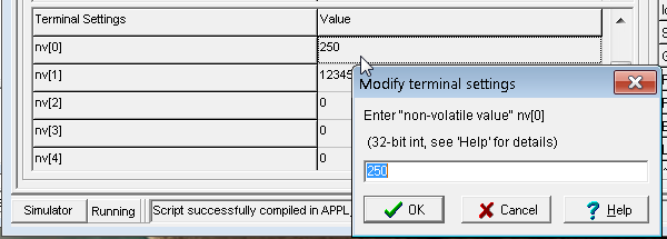
To prevent overwriting a certain nv[]-cell in the target's EEPROM when loading a new application (*.cvt or *.upt), simply clear those values in the corresponding cell in the programming tool's table titled 'Terminal Settings' on tabsheet 'Settings'. Empty cells (without numeric values) will be skipped, when the device firmware imports a new application from a file, via CAN or local network. In other words, those EEPROM cells will remain unchanged.
Commands to access the 'non-volatile Array' (EEPROM) also exist in the script language.
- Note for developers:
- Internally, cells which shall not be overwritten in the target will have their values set to 0x8000FFEE.
That's the internal code for an 'invalid integer'. If, during a simulator session, your application (script, etc) overwrites this value before saving the application as a *.cvt or *.upt file, your edited nv[]-values in the string grid shown above will be lost.
return to the overview of numeric functions
Functions to read (onboard-) analog and digital inputs
- Not all terminals have (onboard-) digital inputs - see Feature Matrix !
- For advanced applications, poll the digital inputs in the script language,
e.g. use a fast running timer
to sample the inputs (system.dwInputs) every 10 milliseconds.
That way, you can use them to measure low frequencies, poll incremental encoders, etc.
Syntax:
-
inp - Returns the states of all (onboard-)digital inputs, combined as bits in a byte.
-
inp1(since 2003-04) - Returns the state of the first(!) digital input. Result is either zero (0) or one (1).
-
inp2 - Returns the state of the second digital input. Result is either zero (0) or one (1).
The total number of available digital inputs, and their pin numbers on the
digital I/O connector can be found in the hardware manual of your terminal
(outside the scope of this document !).
The same applies to the analog inputs:
-
ain1or
ain2 -
Returns the raw (non scaled) result of a 10-bit analog/digital conversion for the specified analog input.
The value range is 0...1023 (210-1).
The input voltage divider (between connector and input to the A/D converter) is hardware dependent.
For the MKT-View II, the input range was 0 to 15 Volts, i.e. ain1=1023 meant 15 V on the 1st analog 'on-board' input).
For other devices, consult the data sheet for the type and scaling range of the analog inputs.
In the script language, onboard analog inputs can be polled as a floating point value (0..1) via system.analog_in[0..3].
In the programming tool, the onboard analog inputs can only be emulated. To set a value, select
'Options' .. 'Simulated analog Inputs' in the main menu, select the channel (index 0..3), and enter the new value (0..100 %) in the edit field. Even arbitrary waveforms can be realized by entering numeric expressions here: The expression
50 + isin(ti_ms/3)/655
will produce a sinewave with 100 % amplitude ("full swing" for the simulated analog input), and a frequency of approximately 1 / ( 1024 milliseconds * 3 ) = 0.326 Hz .
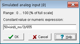
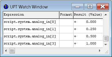
Simulation of an onboard analog input in the programming tool, and display of the analog inputs in a watch window
See also: overview of interpreter functions
; commands to control digital outputs .
Functions for the rotary encoder knob (rot.xxx)
Note: Only some devices (e.g. MKT-View) have a rotary encoder - see Feature Matrix !Usually, the rotary knob is used to navigate through the menus like the up/down keys on other keyboards. Pressing the knob acts like the ENTER key. On devices without touchscreen(*), a short double-click toggles the function of the rotary knob between "Cursor up/down" and "Cursor left/right" (required in edit fields). When the user turns or pushes the knob, the firmware usually places the equivalent keyboard codes in the keyboard buffer.
If the terminal's firmware supports the Rotary Encoder, you can use some interpreter functions (and procedures) to control the rotary knob for "special purposes".
The following numeric functions may be used to read values from the rotary encoder:
- rot.f
-
Returns or modifies the current "function" of the rotary knob. Possible
values:
rot.f knob turned CCW ("left") knob turned CW ("right") Remarks 0 no cursor key produced no cursor key produced
1 CURSOR UP CURSOR DOWN navigate through menu 2 CURSOR LEFT CURSOR RIGHT move through string 3 CURSOR DOWN CURSOR UP increment/decrement values 4
reserved
To change the cursor codes produced with the rotary knob, use a formal assignment like
rot.f=2
Note: rot.f only affects the generation of 'cursor key' codes, but not the following function:
- rot.p
-
Returns the current position of the rotary encoder as an integer value.
Note: Assigning a new value to 'rot.p' internally changes an offset, but does not affect the current menu item etc.
If the rotary encoder is turned clockwise, rot.p will be incremented. Counterclockwise decrements. The first encoder we used produced 20 steps for a full revolution (360°).
Note: As mentioned above, you don't have to poll the encoder yourself if you only want to use it in menus (for "navigation") or to edit numerical values. The terminal firmware will do that itself, as long as you don't setrot.fto zero.
- rot.l
-
Returns 1 (= TRUE) if the knob has been turned LEFT (ccw) since the last
call of this function.
In other words, calling this function has a side effect: It clears the flag, so don't call this function from more than one place. To read the encoder position without side effects, userot.pinstead, and compare it with the "previous" value stored in a local variable.
- rot.r
-
Returns 1 (= TRUE) if the knob has been turned RIGHT (cw) since the last
call.
See notes on the side effect of this function (same as forrot.l) - rot.lb, rot.rb
-
Similar like "rot.l" or "rot.b", but these buffered functions return TRUE
for every 'step' of the rotary button. If, for instance, the button has been
turned left 5 steps very quickly, "rot.lb" returns TRUE for 5 consecutive
calls, while "rot.l" only returns TRUE one single time.
These functions were designed for switching display pages with the rotary encoder, whenever the operator shall select a display page with a quick turn of the button (see "page-scan" example).
Like many other functions (which were designed to be used in event definitions), calling this function has a side effect:
It clears the flag internally. To read the encoder position without side effects, userot.p.
Note: In the terminal simulator window, you
can (optionally) use the mouse wheel as a replacement for the rotary encoder.
Alternatively, use CTRL-Cursor up/down to replace the encoder. This only
works while the simulator is running, and the simulator window is focused.
(*) In devices with a
touchscreen, a double-click with the encoder
button opens the virtual keyboard. To move the edit cursor (inside an edit
field), just tap on the new location.
See also: Overview of Keyboard Functions,
Intercepting rotary encoder events via script .
Functions for the analog joystick (jx,jy,jxr,jyr,jc)
Because only very few devices have a built-in analog joystick, the interpreter functions to poll the joystick have been moved into a separate document.Display Interpreter Commands
The UPT firmware contains an interpreter for the following purposes (here sorted by category, not to be confused with the script language):- event reaction methods, which are usually "goto" or "call" -commands
- graphic output commands for complex display pages
- commands to control signal LEDs and backlight,
- commands to control the UPT's digital outputs ,
- commands to control the four "User"-timers,
- commands to access any 'named display element' on the current page,
- assign command to set a new value of a variable, variable references,
-
save non-volatile values in EEPROM,
- CAN-transmit command which allows you to SEND any CAN-Telegram you like (once),
- PDO-commands (and functions) for "programmed" access to process data channels,
- SDO-commands and -functions for remote SDO-accesses without using extra variables,
-
OBD-commands and -functions to access the
own (local) CANopen-object-dictionary,
- Commands to open screens from the terminal's SYSTEM MENU, and invoke other "system" functions (like sys.reset)
- query and control the rotary encoder (only on certain terminals), page-scan-mode, etc
- commands to control the diagram (only on certain terminals..)
- commands for the serial interface, and (optional) reception of GPS data (NMEA0183 through RS-232)
- commands and functions to control a GSM modem (optional feature, for MKT-View only)
-
other special commands for different purposes:
CAN reset, beeper, logger,
popup messages, etc
(use your browser's "back"-button to return here !)
See also:
- overview of interpreter commands (alphabetically sorted)
- overview of numeric functions
- Script Language (with editor/debugger, compiler, and runtime library; only for certain devices with 32-bit CPU and plenty of ROM)
Some interpreter commands expect a list of parameters, others don't require any parameters.
Most parameters can be numeric expressions . (use your browser's 'back'-button to return here !). Please don't confuse these display interpreter commands with the script language - the script language is compiled before execution, and thus both are not compatible. However, if you really need to, you can invoke display interpreter commands from the script (but try to avoid that).
For testing purposes you may send commands to the interpreter using the status bar of the programming tool (not sure if this feature still exists, it was intended only for debugging).
In the UPT programming tool, you can get
command-specific help by pressing F2 while
the cursor and mouse is in an edit field with a valid interpreter command.
Overview of display interpreter commands
(roughly ordered by alphabet; for categories see the list above)- audio.xxx (commands to control the optional audio recorder)
- CAN reset, CAN transmit, reset
- csim. : Module prefix for CAN simulator commands. Only exists in the programming tool.
- draw mode, display inversion
- dia.xxx Diagram commands (and -functions; only for certain devices)
- dim : modifies the dimensions of an array (up to 3 dimensions)
- disp.<name>.<component> : Access parts of a display element definition during runtime
- goto, call, return
- gps.xxx (commands for an external GPS receiver), gsm.xxx (GSM/GPRS modem control)
- hk(handle key), inserts a character code into the keyboard buffer
- co(color), icon, line, pixel, frame, fill, cls , gf, disp (graphic commands)
- LED's, backlight control, digital outputs, beeper
- menu mode, menu item
- nvs(non-volaile storage)
- rot.xxx (rotary knob),
- sdo (service data object), obd (object dictionary),
- logger (to control the optional CAN-Logger), ....
- nscan (node-scan) is a special function to scan for nodes in a CANopen network
- page-scan control
- play, beep generate simple tone sequences ("beeps") using a pulse-width modulated output
- power=1 : Command to set the 'Power-Good'-flag (MKT-View "Plus" only)
- rem: begins a comment field in a command line or similar
- script.XYZ : Invokes the procedure (or function) named 'XYZ', in the script language.
- sys.menu, sys.show_icons, sys.edit_contrast , sys.reset and other "system control" commands
- signals.timeout, signals.tx_enable : Options for CAN-Signals ("CANdb").
- timer procedures
- udp.xyz : commands (and functions) to communicate via Ethernet using UDP (User Datagram Protocol)
- var(<name>) : Access a variable per reference (for example, using the name in another variable)
- vkey.xyz : Controls the virtual keyboard (only available for devices with touchscreen)
See also: overview of numeric
functions;
User-defined functions and procedures in the script language
Goto, Call and Return-Command (g,c,r)
These commands for the UPT's built-in command interpreter are used to switch between pages of your application. All of these commands must be entered in abbreviated form (single letter).- Syntax:
-
goto: g<page-number> or g"page-name"
call: c<page-number> or c"page-name"
return: r
- Examples:
-
g(0) : REM jump to display page zero

      g(pn+1) : REM jump to next display page

      g(pcnt-1) : REM jump to last display page

      g"MainMenu" : REM jump to a page named "MainMenu"
"Goto" and "Call" both switch to another display page, which may be defined by the page-number or (preferrably) by the page-name.
"Call" also saves the number of the current (old) page on a special "call-stack" before switching to the new page. The "called" page may switch later switch back to the "calling" page using the "return" command.
"Call" + "Return" should always be used together. If you enter a page with a "call", you should also "return" to the caller and not jump back to the caller with a "goto" (this would cause an overflow of the call stack, furthermore it does not make too much sense).
The reason to use "call" + "return" instead of "goto" is when many different callers use a common "subpage" (like a "subroutine"). After the "subroutine" has done its work (for example display an error message and wait for a key), the normal operation can resume.
Note: Neither "goto" nor "call" have an effect if the target (=new) page
is the "current" (=old) page, no matter if called "by number" or "by name".
Commands to set Menu Mode and Menu Index (mm,
mi)
These commands can be used to switch the current display page into edit-
or navigation mode, and to set the current menu item (or edit field, which
is the same internally).
-
Syntax:
-
mm( <new menu mode>)
mi( <new menu index>)
mi( <new menu index>)
(the menu index 'mi' is a current number for the menu item, depending on the order of menu lines in the definition of a display page)
Valid menu modes (mm) are:
- 0 = "off", neither selection bar nor blinking cursor block are visible
- 1 = "select", the current menu item (or display line, maybe an edit field) is inverted, and the user can move the selection bar with the cursor keys
- 2 = "editing", the blinking cursor is visible on one of the editable digits of a number. Only possible if it's an edit field !
Usually, when switching back from "editing" to "selecting" or even "off", the contents of the current edit field is written back into the associated variable. To abort editing (i.e. switch back without applying the edits), use the command mm(8) instead of mm(0) . Note: This is only available in devices with firmware compiled 2008-11 or later.
- 8 = "abort editing" and switch back into the "off" state.
- 9 = "abort editing" and switch back into the "select" state.
In the script language, "mi" can be accessed as display.menu_index, and "mm" can be accessed as display.menu_mode .
See also: Using display lines as menu items
"LED"-Command
The UPT's firmware of some variants of the User Programmable Terminal has one command to control the built-in signal-LEDs (if the terminals has LEDs).The syntax of this command depends on the terminal capabilities. Here the simpler format for terminals with monochrome LEDs:
- Syntax:
- led( <led-number>, <led-blink-pattern> )
- or abbreviated:
- le ( <led-number> , <led-blink-pattern> )
- Parameters:
- <led-number> is the index of the LED that shall be switched: 0=1st LED, 1=2nd LED, ....
<led-output-pattern> is an eight-phase-code for the LED blink "rhythm". Every bit of this pattern controls a 100ms-Interval. After a cycle of 8 * 100ms the whole cycles starts again from the beginning. All LED-blink-cycles are "synchonized": that means, if two LEDs have the same blink-pattern they will flash exactly at the same time.
Here are some useful blink patterns:
- 0x00 LED is OFF (this is the default state after power-on)
- 0xFF LED is permanently ON
- 0xF0 LED blinks slowly: 400ms ON, 400ms OFF and so on.
- 0x55 LED blinks quickly: 100ms ON, 100ms OFF and so on.
- 0x01 LED gives short "flash pulses": 100ms ON, 700ms OFF and so on.
Certain terminals ( e.g. MKT-View II / III / IV ) contain RGB LEDs . In that case, use this syntax to drive the LEDs:
- Syntax:
- led( <led-number>, <led-blink-pattern>, [ <red intensity>, <green intensity>, <blue intensity> ] )
The optional red, green, and blue intensities allow driving the LED in any RGB colour mixture (aka "true colour"). The intensity range is 0 ( off ) to 255 (max) . If the R/G/B intensity is not specified, the previous value is used. By default, the three colour components are set to 127 (= half level), resulting in a white(ish) colour.
Examples for RGB LEDs:
-
led( 0, 0xFF, 0xFF, 0xFF, 0xFF )  : REM 1st LED bright white,
      permanently on

      led( 1, 0x55, 0xFF, 0x00, 0x00 )  : REM 2nd LED bright red, flashing
      rapidly

      led( 2, 0xF0, 0x00, 0xFF, 0x00 )  : REM 3rd LED bright green, blinking
      slowly
led( 0, 0x0F, 0x00, 0x00, 0xFF )  : REM bright blue, blinking
      slowly (2nd phase)
led( 1, 0xFF, 0xFF, 0xFF, 0x00 ) : REM bright yellow
led( 2, 0xFF, 0xFF, 0x00, 0xFF ) : REM bright purple
led( 0, 0xFF, 0x00, 0xFF, 0xFF ) : REM bright cyan
Notes:
- The demo program "MV2_DEMO.CVT" (MKT-View II Demo) contains some of the LED driving commands shown above.
- Since the RGB LEDs are not directly connected to the microcontroller (they use an internal serial port instead), it may take a short while until the new colour becomes effective. For that reason, don't try to create flashing effects by sending new LED colours every millisecond. Instead, use the blink pattern if you need to.
- In the "off"-state of the blink cycle, the RGB LEDs will not be turned completely off. They are switched to a very dim "glow", depending on the ambient light settings (by default, all three components are set to about 6 % of the maximum value. This is sufficient to see the illuminated function keys at night)
- In the script language, there is a similar command (system.led) to control the RGB-LEDs from your application.
Backlight control commands (bl, kl)
On certain devices the LCD backlight can be controlled from the UPT application
(since May 2002).
Depending on the hardware, the backlight can either be switched on or off,
or varied in intensity (MTG320).
- Syntax:
-
bl(1) sets the minimun possible backlight intensity (barely visible),
bl(255) sets it to the highest possible intensity,
bl(1..254) only works on certain terminals to set the illumination to 'mid-range'.
Note: You can set the default LCD backlight intensity to a fixed value from the terminal's setup menu if you don't want to use an interpreter command.
For certain terminals with electroluminescent foil (EL) for keyboard illumination, there are some commands to turn the keyboard illumination on or off. Because EL-panels have a very limited lifetime, the illumination will always be turned off after a certain time of no activity on the keyboard or rotary switch.
- Commands to control the keyboard illumination:
-
kl(0) turns the keyboard light off, and also stops the keyboard-light-off
timer.
kl(N) turns the keyboard light on for (N) seconds. Example kl(60) turns the keyboard-light on for at least one minute.
By default, the keyboard illumination goes off after 600 seconds (if no key is pressed). This timeout-intervall is overwritten with the kl-command. Modifying this interval via system-setup (as for the LCD backlight) is not possible.
See also: more interpreter commands
Invoking the compiled script from the interpreter
The prefix 'script.' tells the display interpreter that
a procedure (or a function) written in the script language shall be called.
- Example (in a display interpreter commandline):
-
script.SetLanguage(LANG_GER)
In the above example, 'SetLanguage' is the name of a user-defined
procedure
written in the script language, which expects a single integer value
(here: LANG_GER, a constant defined in the script sourcecode):
- Example (script sourcecode from the "Multi-Language-Test") :
-
const

         // 'language codes' :

         LANG_ENG = 10000; // internal language code for 'english'

         LANG_GER = 20000; // internal language code for 'german'

         LANG_ARA = 30000; // internal language code for 'arabian'

      endconst;
...
//------------------------------------------------------------

      proc SetLanguage( int iLanguage ) //
      user defined procedure .

        // Sets the new 'current language' (LANG_GER, LANG_ENG, etc).

        // Called from the DISPLAY INTERPRETER, for example

        // as reaction to pressing certain buttons

        // in the display application.

        // Note: Since 2011-09-19, when invoking a script function

        // from an interpreter commandline, the SCRIPT CONSTANTS can be

        // used in numeric expressions evaluated by the DISPLAY INTERPRETER
      !

        if( language !=
      iLanguage ) then

          // Display language has been modified:

          language := iLanguage; // set NEW language in a global var


      display.exec("cls");
      // redraw the entire display page

        endif;

      endproc; // end SetLanguage()
See also ( about interaction between script and display application ) :
- Accessing display variables from the script
- Accessing script variables from the display interpreter
- Invoking script procedures from the display interpreter
-
Invoking
script functions from display pages (with a backslash
sequence in the format string)
Details about the script language are in an extra
document. The script language is only available for devices with
at least a 32-bit CPU, and firmware compiled after year 2010 !
Special display commands
The following "special" display interpreter commands are used to display graphic elements on the LCD.- co(<fg>,<bg>) sets foreground and background colour for some of the commands below
- icon (ic) draws a small image ("icon")
- line (li) draws a line
-
pa(X, Y, text) prints a text string at the specified graphic coordinate.Deprecated, only for the old UPT515, don't use ! - pixel (pi) sets a single pixel
- frame(fr) draws a rectangular frame
- fill(fi) draws a solid rectangular shape
- gf fills a rectangular area with a colour gradient (gf = gradient fill)
- cls(cl) erases the screen and draws all "display fields"
- popup opens a small popup window in front of everything else
To set some additional parameters that affect the graphic drawing commands, you may use the following commands:
- dm sets the draw mode for graphic output commands.
- zo(X,Y) sets the zoom factor for drawing icons.
These commands must be entered in an abbreviated form into one command line. They are processed by the command interpreter .
- Example (from the "Dead-Pixel-Test" for MKT-View II, programs/DeadPix1.cvt, filler command for the "special background" ) :
-
co(BGCol,BGCol) :
      fi(0,0,xmax,ymax,0,0)
If some graphic elements or text lines on the screen overlap, you should be aware of their drawing order.
Only a few devices with 32-bit CPU (like the "MKT-View II") support the following commands/functions:
- disp.<NAME>.<COMPONENT> can be used to access a certain display element on the current display page. This allows you to modify parameters like the element's colour, position, format string, etc during runtime, which can otherwise only be modified with the programming tool. (Note: This only works because the "current display page" is loaded from FLASH ROM into RAM). Details about this function can be found here .
- rgb( <red>, <green>, <blue> ) : Function to mix a colour from the red, green, and blue component. Details and an example here.
See also:
Drawing icons via command(ic)
This old graphic command was used to draw a small picture ("icon") on the screen.If has long been superseded by a display element, but still exists for compatibility reasons.
Syntax:
ic(<icon-name>, <x-position>, <y-position>)
The icon-name must match the name that you defined on the icon-page. Otherwise the display-list-interpreter in the programming too will generate an error. If the icon name is a simple string constant, it must be enclosed in parenthesis as usual (otherwise the interpreter would think it's a string variable).
- Example:
-
ic("stopbtn1",280,10)
Note: Since May 2000 you can also display icons in the format string of a standard display line. This is much easier than using the icon-command, because the position of a display line can be moved with the mouse in the LCD simulator window.
Devices with colour displays support drawing transparent bitmaps. To draw a transparent bitmap, you must specify the colour of all transparent pixels in the parameter list of the icon command, using one of the colour values specified here .
- Example to draw a transparent icon (works on colour displays only) :
-
ic("mkt_logo",100,40,t=7)
In devices that support the script language, the first parameter ("icon-name") may in fact be the name of an object declared as tCanvas in your script. The image (contained in the 'Canvas' object) will be painted at the specified position (x,y), unless your script hasn't generated it at runtime yet.
Setting colours for graphic commands (co)
This command also still exists for the compatibility reasons. You don't need it, because colours can be easily assigned to display elements in the programming tool.- Syntax:
- co(<fg>,<bg>)
sets foreground and background colour for the line- and pixel commands mentioned
below. The possible colour numbers are listed
here .
Drawing lines (li)
This ancient graphic command is used to display a graphic line on the screen. Like some other graphic commands, it only still exists for compatibility reasons.Syntax:
- li( <x1>, <y1>, <x2>, <y2> )
- For all devices with graphic display. Draws a thin line (one pixel wide).
- li( <x1>, <y1>, <x2>, <y2>, <width> )
- For devices with 16-bit CPU and 320*240-pixel display. Draws a line with the specified width in pixels.
Drawing single pixels (pi)
This deprecated graphic command is used to draw a single pixel on the screen.- Syntax:
- pi( <x>, <y> )
Hint: To develop 'portable' applications which work properly on displays
with different screen resolutions ("size in pixels"), use the functions
xmax and ymax (implemented 2011-02-25, only for
newer devices). These functions return the max. possible pixel coordinate.
Beware that counting starts at x=0, y=0 for the left upper corner of the
screen. Thus, for the "MKT-View II", pixel coordinates must be between 0
and 479 (=xmax), and y between 0 and 271 (=ymax).
The same applies to other graphic commands which use 'pixel' corrdinates.
Drawing rectangular frames (fr)
This outdated graphic command was used to display a rectangular frame on the screen.If can be replaced by a graphic element (e.g. non-filled polygon).
The interior of the frame will not be affected by this command (it remains unchanged).
Syntax:
fr( <x1>, <y1>, <x2>, <y2> )
where
x1 = left border
y1 = top
x2 = right border
y2 = bottom
The FillRectangle-command (fi)
Fills a rectangular shape on the screen.
- Syntax:
- fi( <x1>, <y1>, <x2>, <y2> [ , <pattern0> , <pattern1>] )
- with
-
x1=left border, y1=top, x2=right border, y2=bottom,
pattern1, pattern2 = optional "filling" pattern, default=0xFF
All "old" contents of the rectangular area will be overwritten by this command, unless you use a draw mode that does not write both display "pages" (=blink phases).
The optional filling pattern allows drawing rectangles with different shades.
Both patterns are 8-Bit-Masks, where a "1"-Bit will be "set", a "0"-Bit will
be reset. <Pattern0> will be used to fill all even graphic lines,
<Pattern1> will be used to fill all odd graphic lines.
- Examples with filling patterns:
-
fi(10,10,30,20, 0xFF, 0xFF) will draw a "solid "black" rectangle
fi(10,22,30,30, 0xFF, 0x00) will draw a rectangle that consists of horizontal lines
fi(10,32,30,40, 0x55, 0x55) will draw a rectangle that consists of thin vertical lines
fi(10,42,30,50, 0x55, 0xAA) will draw a "50 percent gray shaded" rectangle
If you omit the filling patterns, the interpreter assumes that you want to draw a solid rectangle (the used filling pattern will be "0xFF, 0xFF" then).
Note: For displays with 32-bit CPU and TFT colour displays, there is a special
command to create gradient colour fills. See gf .
Setting the 'draw mode' for graphic commands (dm)
This graphic command was used to set the draw mode for all following graphic output commands.The display in older devices (with small monochrome displays) had two "video-pages", which were alternated every 0.5 seconds to achieve "blink"-effects. For newer devices (especially those with colour- or TFT displays), there is only one 'video page' thus blinking effects are impossible.
Syntax:
dm( <new draw mode> )
valid parameters for the draw mode are:
- 0: Standard-output into both video-pages
- 1: "Page1", output only into page 1
- 2: "Page2", output only into page 2
- 3: Blink1 (draw into page1, erase in page 2)
- 4: Blink2 (draw into page2, erase in page 1)
-
6: inverse output into both video-pages .
For colour displays, this is the only supported 'draw mode' besides mode 0 (standard) ! - 7: inverse output only into page 1
- 8: (removed, was 'inverse output into video-page 1, only for small monochrome displays)
- 9: (removed, was 'erase', only for small monochrome displays)
Note: To change the draw mode in a display text line, use the backslash sequence 'm'.
Display Inversion (command 'di')
On certain terminals with 16-bit CPUs, its possible to use this command to
invert
the complete screen.
- Syntax:
-
di=0 no display inversion, black charackters on white background
di=1 display inversion, white charackters on black background
(In contrast to the 'dm' command, which only affects the characters printed afterwards, the 'display inversion' command always affects the full screen. The inversion is done by hardware on certain terminals. It is quite fast, and can be used to let the screen flash rapidly to catch the user's attention. This is not possible for all displays, see dialog "supported graphic functions" )
The CLearScreen-command (cls)
This graphic command performs the following actions during the next display page update:
- It erases the complete screen
- All display lines are drawn again
- After the display page is complete, the screen buffer will be transferred to the LCD screen.
This command will only be required for complex display pages, for example if you have plotted lots of pixels and want to erase them all (analyze the "Pixel Plot"-example for details !). The "cl" or "cls" command also raises the Page Redraw event (pr) which can be used for very special applications.
Usually, this command is not necessary because the screen will be erased when switching from one display page to another.
See also: more interpreter commands
Gradient Fill command (gf)
Since 2007-12, new terminals with 32 bit CPU and TFT colour displays support a gradient filling command. The syntax is similar to the fi command (filled rectangle) :
Syntax:
gf( <x1>, <y1>, <x2>, <y2>, <orientation>, <colour1>, <colour2> )
- with
-
x1=left border, y1=top, x2=right border, y2=bottom,
orientation: Reserved (no function yet). One day, this value will specify if the gradient runs from top to bottom (=default), from left to right, or other special applications.
colour1 = start colour value
colour2 = end colour value
- Example to fill the entire screen with a colour gradient from green to blue:
-
gf( 0, 0, xmax, ymax, 0, #070, #007 )
The colour values can be any of the UPT "standard colours", or -depending on the hardware capabilities- any RGB mixture. Details about colour values can be found here here .
Note: Graphic buttons can be background-filled with a colour gradient as explained here. You don't need the "gf" command to add gradient-filled buttons in your application. But, like the gf-command, this only works for terminals with 32-bit CPU and TFT colour display.
Functions to retrieve information about the screen
Note: The functions mentioned below were implemented in 2011-03-25. They don't work on older displays like "MKT-View (1)", where the screen was always 320 pixels wide, 240 pixels high, and monochrome.
- xmax
-
returns the maximum possible horizontal coordinate.
x=0 is on the left edge of the screen, x=xmax (typically 319 or 479) is at the right edge.
- ymax
-
returns the maximum possible horizontal coordinate.
y=0 is on the upper edge of the screen, y=ymax (typically 239 or 271) is at the lower edge.
See also: interpreter commands (overview),
numeric functions (overview),
graphic commands .
Timer commands and functions in the display interpreter
The display-interpreter(*) has some built-in functions and procedures to control four "User Timers". These timers can be used to generate time intervals of up to 65534*100ms (which is more than one hour). These timers are intended to produce events , but you may also use them for any other purpose.(*) Devices with script language support more flexible timers than those listed below.
The CAN simulator also has similar timer functions.
Timer procedures
- ts0 ... ts3 (timer start)
-
Starts one of the four "User Timers" for a given time interval. The timer
will count down from the starting value to zero, when it generates a timer
event. Starting a timer again before it reaches zero will prevent the timer
event. The maximum time for a user timer is 65534 ( * 100 ms).
Syntax: ts0(<timer starting value in 100ms>)
Example: ts0(40) starts the first timer for a time of 4 seconds. After 4 seconds there will be a "t0" event which you can handle on one of your event definitions (global or local). - tr0 ... tr3 (timer reset)
- Resets one of the four "User Timers". This will stop the timer and prevent the generation of a timer event. Internally, a timer that has been reset contains the value 0x0FFFF which means "stopped". This value is the default value for all timers after power-on.
Timer functions
The following timer functions are currently implemented in the UPT's display interpreter (*). They return a boolean or numeric result.
- t0 ... t3 (t0 ... t9 for firmware compiled 2012-04-16 or later)
-
Checks if a user-timer has "run off", that means Timer 0 ... Timer 3 has
been decremented from 1 to 0 . Returns:
Zero (=FALSE) if the timer is not running or has not yet reached zero,
One (=TRUE) if the timer has counted down to zero (where it stops) .
Note: The flag "timer expired" is not automatically cleared by reading it !
To clear the "timer-has-run-off"-event, use the command tr0...tr3 (explained above) . Some examples:
Event: t2 // is Timer 2 expired ?
Reaction: tr2 : goto "Timeout" : REM clear timer2 and jump to the "timeout" display
The interval timers (t0..t3 or t9) operate in single-shot mode. To fire periodic events, a timer may be restarted in the reacion method. Example:
Event: t2 // is timer 2 expired ?
Reaction: beep(1000,5) : ts2(10) : REM short beep, and restart timer #2 for the next 1-second interval
- tv0 ... tv3 (timer value)
-
Reads the current value of a user-timer. This value runs from the started
value down to zero (decremented every 100 ms).
- ti (Time since power-on in 100-ms-steps)
-
Reads the current "system clock" as a 32-bit value. The system clock is a
32-bit-counter incremented every 100 ms. It does not depend on the four
"user"-timers and can neither be stopped nor modified by the user program.
After more than 6 years of uninterrupted operation of the User Programmable
Terminal, this value will become negative because it will be incremented
from ((2 power 31)-1) to (2 power 31) which is a negative value for
32-bit-Numbers. After power-on of the UPT, the global time always starts
at zero.
Some demo-programs use this function to show a company logo for a short while after power-on.
- ti_ms (Time since power-on in milliseconds)
-
Reads the current value of a system timer, scaled into milliseconds.
Similar as 'ti', this timer does not depend on the programmable user timers, and can neither be stopped nor started via command (it is "read-only").
Approximately 2^32/(40000Hz*60*60) =: 29.8 hours after power-on, the 32-bit timestamp generator wraps around to zero, causing a step in 'ti_ms'. After each power-on or system reset, this timer starts at zero (it is not battery backed-up).
A few demo applications use this timer (ti_ms) to calculate 'very dynamic' values, which change once every millisecond (in contrast to 'ti' which only changes every 100 ms).
In the script language, system.ti_ms is an equivalent function.
-
tsim_ms (time since start of the CAN-simulation in milliseconds, as integer value),
tsim (time since start of the CAN-simulation in seconds, as 'double')
-
These two functions only exist in the programming tool. They are used to generate time-dependent
stimuli
(in the form of numeric interpreter expressions) for the generation of CAN signals. In contrast to ti_ms,
the value returned by tsim_ms (and tsim) re-start at zero whenever clicking the
CAN-simulator's "Run" button. Also, before starting the CAN signal simulation,
values returned by 'tsim' and 'tsim_ms' are stuck at zero. Thus, tsim_ms
can deliver a 'ramp-up' function for the simulation (like a "mileage travelled", etc)
See also: Overview of interpreter commands,
numeric functions .
Page-Scan mode (controlled by the display interpreter)
Page-scan mode can be used to automatically switch between two or more display pages, timer-driven; but without the need to program extra event definitions. The page-scan mode can be controlled via interpreter:- pscan=N
- Turns page-scan mode on. N is the page-scan interval in SECONDS. For example, pscan=5 switches to the next page (of the page-scan-sequence) every 5 seconds.
- pscan=0
-
Turns page-scan mode off. This is the default after power-on !
- pscan.next, pscan.prev
-
Switches immediately from the current page to the next (or previous) page
belonging to the page scan sequence.
These commands were designed to "zap" through certain display pages with softkeys or (where applicable) with the rotary knob).
Notes and hints:
- If a page shall belong to the page-scan-sequence, set the checkmark "include this page in the pscan-sequence" on the Display Page Header tab. Only those pages which have this flag set, are included in the page-scanning cycle.
-
For manual page-scanning with the rotary encoder knob, use two global events
as in the following example:
Event Reaction rot.lbpscan.prevrot.rbpscan.next -
To toggle periodic page-scanning on and off, you may use a softkey
(programmable button) with this command:
pscan=5-pscan
How does this work ? 'pscan' can be accessed like a variable, it is originally 0 (zero). The above command sets pscan to 5 if it was zero, and 0 if it was 5. You can also change the button's caption, like "Scan" or "Stop". The sourcecode for such a button may look like this:
\btn(55,50,$002,(pscan>0)?"Stop":"Scan",59,pscan=5-pscan) - To query the current value of the page-scan-timer, use pscan.timer . This is a countdown-timer. Unit is 0.1 seconds.
-
If any key is pressed during page-scan, the page-scan-timer will automatically
be reloaded with the double interval time. The effect is: Page-scan
pauses as long as the operator presses keys, but it is not turned off
completely.
- In the script language, "pscan" has been replaced by
display.page_scan .
See also: Overview of interpreter commands,
numeric functions .
The assign-command (@)
This command is used to assign a new value for a variable (or a variable-like command, which uses a formal assignment to "modify something").Devices with a firmware compiled after 2010 don't need the '@' ('at' character) before the name of the destination variable anymore - the interpreter checks the operator after the destination variable, and if it's the 'assignment operator' ( := ), it will evaluate the source expression, and assign the result to the destination variable without the '@'.
Syntax:
@<Varname> := <expression>
Example:
@Ypos := (Voltage*63)/230
Notes:
- You can only assign values to variables that have been defined in the variable table.
- You should not assign values to variables which get their 'input' values from a communication channel.
- Some of the interpreter's built-in commands can be called with a formal assignment too.
See also: variable references, more
interpreter commands
The "Output"-command (drive digital output[s])
This command is used to control the state of the UPT's built-in digital outputs.There are two different "flavours" of this command:
- out(<8-bit-value>)
- This format is used to control all digital outputs at once. Bit 0 controls the first output and so on.
- outN(<new_state)
-
Controls the state of a single output line; output line (N) numbered from
1...N.
Syntax and channel numbering is compatible with the inp - function. - out(<output_nr>, <new_state> )
- This format is used to control the state of a single output line.
Examples:
- out($FF) turns all outputs on
- out($00) turns all outputs off
- out(0, 1) turns the first output on
- out1(1) also turns the first(!) output on
- out16(1) turns the sixteenth output on
- out(3, 0) turns the fourth output off
- out(out^$02) inverts the state of the second output
- out16(!out16) inverts the state of the sixteenth output.
Notes:
-
There is not only an output-command to set the digital outputs,
but also a function named "out" that reads back the current
state of the digital outputs.
Example:out2returns 1 if the second output is set, otherwise 0 (zero). - Not all devices used as "User Programmable Terminal" have own digital outputs. To access outputs on a remove I/O-module, you must use a communication channel.
- Perhaps your UPT515 only has four digital outputs and six digital inputs.
- The UPT's digital inputs and outputs are "simulated" by the programming tool. The state of the outputs is displayed as round shapes in the simulator window.
See also: more interpreter commands;
functions to read the digital inputs .
CAN Transmit (display interpreter command 'ctx')
This command be used to transmit a CAN telegram with any identifier (11- or 29-bit) and any data-field.We strongly recommend not to use this command, because it is very dangerous to transmit a CAN frame into a network without the knowledge of the "CAN ID management" (which may be defined in a communication profile, or in a CANdb file, etc). Remember these words, when the trolley of your CAN-controlled crane crashes into the factory wall at full speed .. ;-)
The same syntax as for interpreter command 'ctx' (in the device firmware) can also be used for the can_tx() command in the programming tool's integrated CAN simulator.
- The basic syntax of the CAN transmit command is this:
-
ctx( identifier, databyte, ...)
The identifier may be succeeded by ".x" if an eXtended frame (29-bit-ID) shall be transmitted. Without a prefix, the identifier is expected in hexadecimal form; otherwise use the character '#' to tell the interpreter it's decimal. Bit 29 in the identifier is also a flag to transmit an extended frame (hexadecimal mask 0x2000000 ORed to the identifier value). Note that bits are always counted from zero, so bit 29 is actually the 30-th bit in an integer value.
The data bytes may be hexadecimal constants (by default), or decimal values
(preceeded by '#'), or even numeric expressions, including variables and
function calls (caution, everything which is not "a simple number" must be
embedded in parentheseis). Note: The same format as for the CAN data field
is also used by the UDP-send
command.
A special service has been implemented to send 16- and 32-bit values with
INTEL or MOTOROLA-byte-order:
- .w or .iw = INTEL WORD,
- .l or .il or .dw = INTEL 'LONG' aka 'doubleword' (32 bit),
- .mw = MOTOROLA WORD,
- .ml = MOTOROLA 'LONG' ('LONG' = 32 bit),
-
.flt = IEEE 754 single-precision floating point with INTEL byte order :
first byte = mantissa bit 7..0, 2nd byte = mantissa bit 15..8, 3rd byte = mantissa bit 23..16, 4th byte = exponent . -
.flt_m = IEEE 754 single-precision floating point with MOTOROLA byte order
(very rare these days) :
first byte = exponent, 2nd byte = mantissa bit 23..16, 3rd byte = mantissa bit 15..8, 4th byte = mantissa bit 7..0 .
Note: Floating point formats are only supported on devices with 32-bit CPU.
- Some examples for the "ctx"-command:
      ctx(0x4D2,1,2,3,4,5,6,7,8)          ; preferred notation separated by comma
      ctx(0x4D2 1 2 3 4 5 6 7 8)          ; optionally without comma
      ctx(#1234, 7B 7C 7D 7E 7F 80)       ; DECIMAL ID but HEX-DATA
      ctx($4D2, #123,124,125,126,127,128) ; HEX-ID but DECIMAL Data
      ctx(#1234.x, 11,22,33,44,55,66,77,88) ; EXTENDED frame (29-Bit-ID)
      ctx(#1234.s, 11,22,33,44,55,66,77,88) ; STANDARD frame (11-Bit-ID)
      ctx(0x4D2, $ABCD.w , #32767.w)      ; two INTEL-WORDs ( 2 * 16 bit )
      ctx(0x4D2, $12345678.l , #12345678.l) ; two INTEL-LONGs ( 2 * 32 bit )
      ctx(0x4D2, $ABCD.mw, #32767.mw)       ; two MOTOROLA-WORDs
      ctx(0x4D2, $12345678.ml,#12345678.ml) ; two MOTOROLA-LONGs
      ctx(0x4D2, (ti).il, (ti).ml )       ; TIME for Intel and Motorola
      ctx(0x456, Temp.flt,Pressure.flt)   ; two single-Precision-floats from variables
      ctx(0x456, (1.0).flt, (2.0).flt )   ; two floating point CONSTANTS, INTEL byte order
      ctx(0x456,(1.0).flt_m,(2.0).flt_m)  ; similar but MOTOROLA byte order
More examples can be found in the terminal application 'ctxfloat.cvt', contained in the installation archive.
By default, the ctx command expects hexadeximal numbers. But to eliminate possible ambiguity between a hex number and a name, always use the prefix '0x' or '$' before a hex number. For example, A1 may be a hexadeximal number, but also the name of a variable. But 0xA1 is surely a hex number and nothing else.
Certain terminals have two CAN-interfaces. For these terminals, there are
two different transmit commands. The ctx command always uses
the first CAN interface (the same as ctx1).
- To transmit with the 2nd interface, use the command
-
ctx2( identifier, databyte, ...) -
The parameters for
ctx2have the same meaning asctx.
Certain terminals (with a 32-bit CPU, and firmware compiled 2009-10-30 or
later) may be able to send CAN signals and messages, using definitions imported
from a database for CAN ("CANdb", *.dbc). Details about sending such signals
can be found here.
Last not least, for devices with unlocked 'extended script functions',
CAN messages can be assembled and transmitted via script as shown here.
Warning: As explained above, it may be dangerous to send
CAN telegrams this way, if you are not absolutely sure
what you are doing !
"System" functions and -commands of the display interpreter
The system-functions of the interpreter provide access to some parameters which are usually controlled through the terminal's system menu. They are mostly used for testing and debugging purposes. Only functions which are mentioned here may be used in your application (there are more, undocumented functions, which may not be supported in future versions of the firmware, which must not be used for that reason).-
sys.audio_vol -
Reads or writes the audio output volume aka "Speaker Volume". The same parameter
can be modified (and permanently saved) in the terminal's
system menu.
The function is only implemented in certain terminals with an analog audio output - see feature matrix .
-
sys.click_vol - Only for devices with touchscreen. Reads or writes the 'touchscreen click' volume. The same parameter can be modified (and permanently saved) in the terminal's system menu.
-
sys.lost -
Returns the value of a counter for all lost CAN messages, unhandled interrupts
due to system overload, lost characters from the serial interface, lost events,
etc. This value is read-only. It is a sum from different sources which should
ideally be zero. The most important sources are:
- logged CAN messages
- CAN messages which should be handled by the terminal's protocol handler (but couldn't due to a buffer overflow)
- keyboard events which should be handled by the terminal application (but couldn't due to a buffer overflow)
- characters received from the serial interface (RS-232 with 3964R protocol)
- interrupts requests which could not be handled due to a massive CPU overload (usually caused by heavy bus load)
-
sys.menu(x) -
Can be used to activate a special function in the terminal's system menu
from your application. This function was once used for testing purposes
during software development, but it turned out to be quite useful so the
author never removed it from the interpreter. More info, and a list of all
possible menu numbers (x) can be found here
.
-
sys.edit_contrast -
Opens a special setup screen where the temperature-dependent control of the
LCD contrast can be optimized. This is only required for certain devices
like MKT-VIEW and IPE-VIEW. How to use this "LCD Contrast Curve Editor" is
explained in a separate document. You can use
this command to allow the operator to 'fine-tune' the LCD contrast without
going through the terminal's system menu.
-
sys.poff -
Turns the power off.
Note: Only a few terminals (for example, MKT-View II") are able to turn themselves off through this command.
How to turn the device on again depends on the hardware. For the MKT-View II, details can be found in the description of the terminal's System Menu; see document #85115 (available in PDF format), chapter "Power on/off" .
The script language's equivalent for this command is system.shutdown.
-
sys.reset -
Performs a system reset, which is almost the same as turning the power off
and on again to reboot the terminal. This may be required in certain situations
to re-initialize certain CAN protocols (or to escape from CAN-gateway-mode
on certain terminals).
In devices with script language, this command can be used to switch back from the application which was loaded via system.exec(<filename.cvt>) from the memory card, into the 'App-Selektor' which is loaded from ROM (FLASH) after power-on.
-
sys.set_time -
Opens a screen where the real-time clock can be
set (calendar date and time). Only available on terminals which have a
battery-buffered real time clock.
Note: In the terminal's system menu, the ISO 8601 international date format is used. The date format is YYYY-MM-DD, and the time format hh:mm:ss. Search the web for "ISO 8601" if you need some reasons why to use this format. It is highly recommended to use this format in your application as well !
-
sys.show_icons - Only available on terminals with a 32-bit CPU since 2008. This command turns on the display of so-called system icons, indicating (for example) the state of the memory card, the state of the power supply, the state of the CAN-bus, and the state of the CAN-Logger. Details are in this extra document.
-
sys.t_shutdown( < interval to open the shutdown-window in 0.1 second steps > ) -
This very special, and rarely used command modifies the time (duration) to
open the shutdown screen. If the power-key (which, for most devices, is the
same as function key F1) is held down longer than this time, the shutdown
screen will pop open; in which the operator may chose to shut down the system
(i.e. "turn the power off"). The default value (which the terminal uses without
this command) is 30 * 0.1 seconds.
Of course, this command only exists in devices which can be turned on an off via a button !
Note: Holding the power key down for ten seconds or more will ALWAYS shut down the terminal, without intervention of the CPU (this is a feature of the power-controller which cannot be modified without a major hardware redesign - sorry).
See also: sys.poff (to turn off immediately, without the shutdown screen).
-
sys.vsup -
Returns the actual supply voltage of the terminal, measured
"shortly after the protection diode". For this reason, the value is not very
accurate. You can use it for diagnostic purposes, for example if the terminal
is powered from a vehicle's battery. The unit is 0.1 Volts, so a value of
123 means "12.3 Volts".
-
sys.vcap -
Measures the voltage at the internal buffer capacitors, if the device is
equipped with an internal UPS (Uninterruptable Power-Supply).
Unit is millivolts. The maximum is just below 5000 (= 5.0 Volts, max. ultracap voltage rating). If the device doesn't have an internal UPS, sys.vcap always returns zero.
-
sys.temp - Returns the current temperature inside the terminal, measured with an NTC sensor near the display. The terminal firmware uses this value for the automatic contrast control. You can use it for testing purposes, etc. Note that some displays get very "slow" below -15°C, and don't work properly below -20°C. The value returned by "sys.temp" is an integer number scaled to 0.1°C, so -185 means "-18.5 degrees Celsius".
-
sys.alight -
Returns the current value from the ambient light sensor. Only exists on certain
terminals, for example MKT-View II .
An example which uses this function to automatically switch between "day- and night-design" can be found here.
See also: more interpreter commands ,
script language .
Other special interpreter commands
beep, play (be, pl)Produce tone frequencies with the internal speaker. Only certain devices have a beeper. For this reason, the "beep" and "play" command are explained in another file.
Button Key, Button State (bk, bs)
To query and set the state of the graphic buttons. Not supported by all firmware
variants, therefore: see explanation in another file.
Handle Key (hk)
This interpreter command can be used to simulate certain keystrokes, which
may not be available on the terminal's "real" keyboard. For example, the
command hk("-") sends the minus character to the system's keyboard handler
to invert the sign of the edited value (if an input field is in edit mode).
The command hk(13) has the same effect as pressing the ENTER-(or RETURN-)key.
The argument may be written as a string of characters, or as a numeric value
from the table of system key codes (Note:
not all of the system keys have a dedicated function !).
See also: Keyboard functions .
Node-Scan (for devices with a modified CANopen-protocol implementation / "Mini-Master" )
Scans a CANopen network to fill a list with all nodes, including their node IDs and device names. Described in a separate file, because this function does not belong to the standard functions of a programmable terminal.
Resets the application (and some CAN protocol layers). All variables are set to the power-on values (where applicable). All timers are reset. All pages are re-loaded from the permanent storage medium (usually a FLASH device). The program switches to page zero, like after a power-on.
Commands to control the CAN logger
Explained in another file, because the "CAN logger" is a special feature which does not exist in the standard terminal.
See also: more interpreter commands
The script editor / compiler / debugger
Beginning with the MKT-View II, devices with 32-bit CPU and sufficiently larg memory have a built-in script compiler. Scripts allow developing more advanced display applications, because the 'program logic' can be separated from the 'user interface'. Thus, for new applications, consider implementing the 'logic' in a script, instead of the older event definitions.
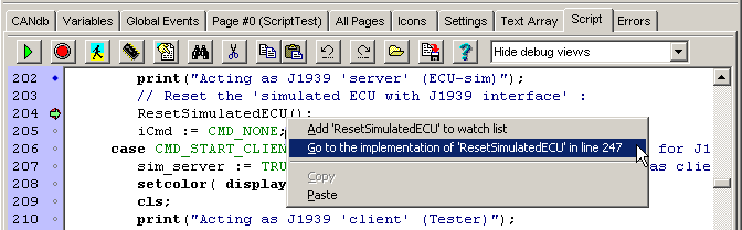
Screenshot of the script editor (in the programming tool, on the 'Script' tab)
Appendix
- Frequently asked questions (separate document)
- Manuals for the programmable terminals (in PDF format)
- Boot Screen (optional graphics displayed after power-on)
- SDO error codes (only for terminals with CANopen)
- CANopen objects inside the terminal ( " " )
- Glossary
- Revision history of the family of User-Programmable Terminals (UPT)
Manuals for the programmable terminals (PDF format)
The following links lead directly to the manufacturer's website (MKT). This ensures you will read the latest version of the document. If your PC is not connected to the internet, you will find (possibly outdated) copies of those files in a subdirectory named 'DOKU' in the folder where you installed MKT's Terminal Programming Tool.- Document Nr. 85110 : General manual for the UPT & CANdb terminal programming tools (for UPT and MKT-Views)
- Document Nr. 85111 : Additional infomation for terminals with CANdb support ( MKT-View +, MKT-View II / III, ..) . So far, only available in German language.
- Document Nr. 85113 : Description of the CAN logger configuration utility. Only contained in the installer of that utility !
- Document Nr. 85114 : Installation of a CAN-bus interface on a PC. So far, only available in German language.
- Document Nr. 85115 : Description of the terminal's system menu
- Document Nr. 85116 : Download protocol specification. For programmers who need/want to roll their own programming tool...
- Document Nr. 85118 : Description of the optional CAN snooper (a simple CAN bus monitor, integrated in some devices)
-
Dokument Nr. 85122 :
Scripting
Language for various (but not all) programmable display terminals by MKT
- Document Nr. 85130 : Getting started with the MKT-View II (slightly outdated, in Memoriam R.V.)
- Document Nr. 85131 : Presentation of the programming tool by its developer (in German)
- Dokument Nr. 85132 : Presentation of the optional CAN logger, and the CAN logger configuration utility (German)
- Again: Most of the above documents are also available locally on your harddisk in the 'Doku' folder, after installation of the programming tool.
Other documents, like hardware specific manuals, catalogues, etc can be
downloaded from the MKT wbsite.
Boot-Screen (optional display of a bitmap while booting)
Depending on the complexity of the application, and the speed of the CPU in the programmable device, a few seconds may pass between turning on the power and the appearance of the first 'programmed' display page, aka 'page zero' .By default, the display shows the initialisation progress (in the form of text messages on the 'console'), or the screen remains dark until the first display page appears. The above behaviour can be configured in the 'System Setup' under 'Display Setup' by setting 'Bootup Display' to 'FALSE' (which means no "bootup messages" shall be displayed on the screen).
In some cases (e.g. when compiling large scripts in the user application), having a 'completely black' screen for a few seconds may be irritating for the operator.
On colour displays, a customized graphics file can be displayed instead, while the display boots, compiles the script, etc:
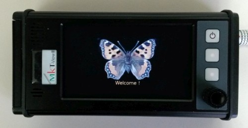
(Example for a customized 'Boot Screen', 240 * 240 pixel, loaded into an MKT-View III)
To achieve this, the display of 'boot messages' should be disabled by setting 'Bootup Display' to 'FALSE'
in the devices 'System Menu / Setup' as shown below:
|
|
→ |
|
→ |
|
→ |
|
(Disabling the 'system' messages during device bootup, here: in an MKT-View III)
To show the customized bootup graphics 'as fast as possible after power-on', a bitmap named 'BOOTSCRN.BMP'
("boot-screen" graphics, (*) ) must be written into the device's internal FLASH.
Similar as user-defined fonts, this file is not embedded in the *.cvt file (application), because
that would unnecessarily blow up the size of any *.cvt file. Instead, the boot-screen graphics can be
copied ('flashed') into the device with the programming tool's integrated file transfer utility.
In the device's pseudo file system, select the destination folder
"font_flash" (the destination folder always appears in the right half
of the file transfer window).
The image file only needs to be uploaded once because the "font_flash" is not erased
when loading a new *.cvt or *.upt application.
 (*) The file BOOTSCRN.BMP must be a standard, non-compressed bitmap.
The colour depth should not exceed 8 bit per pixel, i.e. 256 colours (with palette or in 'RGB332'-format).
The size (in pixels) must not exceed the size of the display (see Feature Matrix).
If necessary, size and colour format can easily be adapted with the freeware utility 'IrfanView'.
To reduce the colour depth in IrfanView, select Image .. Decrease Colour Depth .. 256 Colors (8 BPP).
To adapt the size, select Image .. Resize / Resample.
If the image is smaller than the display, it will be centered on the screen.
The example used here (for medium-sized displays) is contained in the programming tool's 'fonts' folder,
file BOOTSCRN.BMP.
Due to its size of 240 * 240 pixels, it is suitable for the MKT-View III (etc) in landscape- as well as portrait mode.
SDO error codes
The table below shows some error codes that may occur during program upload or download.
Most of these error codes are taken from CANopen DS301 V4.
Some of these errors may also be caused by external devices on the CAN bus.
For a more sophisticated explanation of these errors you should check the CiA literature or other CAN protocol descriptions.
See also: CANopen objects inside the UPT , description of the error page
| Error Code | Meaning |
| 0x05030000 | TOGGLE-BIT NOT ALTERNATED |
| 0x05040000 | SDO-PROTOCOL TIMED OUT |
| 0x05040001 | COMMAND SPECIFIER NOT VALID OR UNKNOWN |
| 0x05040002 | INVALID BLOCK SIZE |
| 0x05040003 | INVALID SEQUENCE NUMBER |
| 0x05040004 | CRC ERROR |
| 0x05040005 | OUT OF MEMORY |
| 0x06010000 | UNSUPPORTED ACCESS TO AN OBJECT |
| 0x06010001 | ATTEMPT TO READ A WRITE-ONLY OBJECT |
| 0x06010002 | ATTEMPT TO WRITE A READ-ONLY OBJECT |
| 0x06010047 | UNSUPPORTED ACCESS, INTERNAL INCOMPATIBLE |
| 0x06020000 | OBJECT DOES NOT EXIST IN DICTIONARY |
| 0x06040041 | OBJECT CANNOT BE MAPPED TO THE PDO |
| 0x06040042 | MAPPED OBJECTS WOULD EXCEED PDO LENGTH |
| 0x06040043 | GENERAL PARAMETER INCOMPATIBILITY |
| 0x06040047 | GENERAL INTERNAL INCOMPATIBILITY |
| 0x06060000 | ACCESS FAILED DUE TO HARDWARE ERROR |
| 0x0606002F | ACCESS FAILED DUE TO CAN ERROR |
| 0x06070010 | DATA TYPES DO NOT MATCH |
| 0x06070010 | LENGTH OF PARAM DOES NOT MATCH |
| 0x06070012 | LENGTH OF PARAM TOO HIGH |
| 0x06070013 | LENGTH OF PARAM TOO LOW |
| 0x06090011 | SUBINDEX DOES NOT EXIST |
| 0x06090030 | VALUE RANGE EXCEEDED |
| 0x06090031 | VALUE RANGE TOO HIGH |
| 0x06090032 | VALUE RANGE TOO LOW |
| 0x06090036 | MAXIMUM VALUE IS LESS THAN MINIMUM VALUE |
| 0x08000000 | GENERAL ERROR |
| 0x08000020 | DATA CANNOT BE TRANSFERRED TO APPLICATION |
| 0x08000021 | .. due to local control |
| 0x08000022 | .. due to device state |
| 0x08000023 | OBJECT DIRECTORY GENERATION FAILS |
CANopen objects inside the UPT
CAN-Bus as part of the manufacturer specific profile of a CANopen object dictionary. The programming tool uses these objects to transfer your "user program" into the terminal via CAN-bus.
There are two, totally different, implementations
of the CANopen protocol in MKT's display terminals: The UPT515 used
a proprietary implementation due to its lack of code memory space, all other
terminals (with 16-bit CPUs and sufficient memory) like the UPT320 uses
a CANopen protocol stack written by SYS TEC.
For the UPT320 (alias "MKT-View with CANopen" and some others), the CANopen Object Dictionary is defined in an EDS file. Some details about the objects in the manufacturer specific profile area can be found in this separate document.
The following is only valid for the old UPT515, which doesn't have enough memory for a full-featured CANopen implementation :
As you upload or download a program into/from the terminal, there may be some error messages with a CANopen-index in the range of 0x5100 to 0x57FF. The possible cause for such errors may be a compatibility problem between an "old" terminal and a "new" programming software (or vice versa). The following table may help to trace such errors:
| CANopen-Index | Contents (beware, some objects only existed in the old "UPT515", while some other objects only exist in newer devices with 32-bit CPU ! ) |
| 0x4001..0x400F | PDO-mappable variables (UPT 2 only, not for UPT515 ! ) |
| 0x5000 | Onboard digital inputs (for a few devices of the UPT 2 family) |
| 0x5001 | Keyboard matrix (for most devices of the UPT 2 family) |
| 0x5080 | MKT's CAN snapshot utility (UPT515 only) |
| 0x5101 | Constants (max number of variables, etc., UPT515 only) |
| 0x5102 | Names of the terminal's keys (UPT515 only) |
| 0x5103 | Settings (number of display pages, etc., UPT515 only) |
| 0x5104 | Run Mode (Run, Stop, Transfer etc, UPT515 only) |
| 0x5105 | current Display-Page |
| 0x5106 | Save Permanent (transfers RAM data to EEPROM, UPT515 only) |
| 0x5107 | Erase some Flash Sectors (used for table-storage, UPT515 only) |
| 0x5110 | CANopen-Konfiguration (SYNC, NMT, UPT515 only) |
| 0x5111 |
Contains the complete "UPT"-Application
for Terminals with 16-Bit-CPU (as strings with "auto-increment" for the line counter, only for terminals with CANopen V4, so not for UPT515). Devices with 32-Bit-CPU can be remotely controlled through this object. |
| 0x5112 | X/YModem file server object (only for devices with 32-Bit-CPU) |
| 0x5120 | CANdb(!) file import history (as strings, UPT515 only) |
| 0x5180 | global Events-Definitions (as strings, UPT515 only) |
| 0x5200..52ff | SDO-Channel-Definitions (as strings, UPT515 only) |
| 0x5200 | Onboard digital outputs (for a few devices of the UPT 2 family) |
| 0x5300..53ff | PDO-Kanal-Definitions (as strings, UPT515 only) |
| 0x5400..54ff | Variable-Definitions (as strings, UPT515 only) |
| 0x5500..55ff | Display-Page-Definitions (as strings, UPT515 only) |
| 0x5600..56FF | Icon-Definitions (hex-coded strings, UPT515 only) |
| 0x5700..57FF | Text-Array-Definitions (strings, UPT515 only) |
| 0x5800..580F | Non-volatile values which can be accessed as "nv[N]" from the
interpreter. UPT515 only ! ! |
The data format of the definition-tables is very similar to the text-file-format which is used to save your UPT-program on a disk drive. In fact, we use the same conversion routines in the UPT firmware as in the programming tool.
Since 2005, some user-programmable terminals use a "large" implementation of the CANopen protocol DS301 V4. For more information about those terminals, read this document.
See also: Usage of Index and Subindex , SDO error codes, CANopen configuration
Glossary
- Babbling Idiot
-
A defective CAN node, which (for example) isn't able to receive, but can
still transmit for some reason. This may lead to an endless transmission
because the "babbling idiot" never sees an acknowledge for his own transmission,
and -as specified by CAN- keeps on trying over and over. A Babbling Idiot
can virtually kill the entire traffic on a CAN-bus, if no special hardware
cuts it off automatically. It can also cause a lot of
error frames (which are sent by other nodes
in response).
- CiA = "CAN in Automation"
-
International users and manufacturers group. Supporter of
CANopen . CAN be found in the internet at
www.can-cia.de .
- CANdb file
-
CAN database file. Another way of describing CAN messages and signals in
a network (totally different from
CANopen).
CANdb is registered trademark of Vector Informatik GmbH. They also offered a tool to edit CANdb files, but it seems to have disappeared (at least as a standalone-product). A standalone CAN database editor is also available from Kvaser .
- CANopen
-
Is an 'open' industry standard by CiA which descibes
a huge set of transmission protocols, data types, and how data in a device
are organized in an object dictionary. DS401,
for example, is just a tiny fraction of CANopen.
- CVT
-
CAN-Viewing Terminal. An arbitrarily
chosen file extension for certain terminal applications. In contrast to UPT,
files ending with 'CVT' are files for terminals with CANdb functionality,
while 'UPT' terminals support CANopen. The first terminal which used 'CVT'
files was the IPE-View / MKT-View terminal.
Later (in autumn 2009) someone claimed that the display terminal should be able to transmit CAN signals (described in a CAN database file). However, the file extension 'CVT' (for CAN Viewing terminals) remained unchanged, even though these displays are in fact no 'viewing terminals' but controllers .
- Device Profile
-
a standardized description of a device, here: as part of
CANopen from "CAN in
Automation".
- DS401
-
CANopen Device Profile for I/O-Modules. A document
from "CAN in Automation".
- Error Frame
-
indicates that "there is something wrong" in a CAN network. Error Frames
can be displayed by the programming tool (!), if a suitable CAN interface
/ CAN driver is used.
- Function
-
A built-in subroutine of the display interpreter that returns a value. Can
be part of a numerical expression. Its name always begins with a lower-case
letter. A function is not the same as a
procedure !
- MKT-View
-
A programmable display-terminal for automotive use. Not intended
to be a control terminal, though often (ab-)used this way. The first
firmware for these terminals did *not* support CANopen, but could be configured
via CAN database files. The files which can be loaded
into the MKT-View terminal have the extension
CVT.
- OD
-
Short for Object Dictionary. Sometimes (- better? -) called Object Directory,
but CiA decided to call it CANopen Object Dictionary.
The OD contains "everything" which can be accessed through CANopen Service
Data Objects (SDO). An electronic description of a CANopen OD is the EDS
file (electronic data sheet), particular values from an OD are saved in a
DCF (device configuration file).
- PDO
-
Process Data Object. Used to transport several different values in a particular
CAN message in a CANopen network. Often sent periodically or event-driven.
Only certain data types can be exchanged via PDO (in contrast to
SDO, which allows to read and write any
data type - including strings, etc) .
- Procedure
-
A command of the system interpreter. It does not return a value and
can not be part of a numerical expression, because a procedure
is not a function.
- SDO
-
Service Data Object. Used to access the OD in a CANopen device via CAN bus.
Usually used to parametrize a device via CAN, but not to communicate with
a CANopen slave during 'normal' operation (in contrast to
PDO) .
- Suitable text editors
-
.. are plain text editors which do not replace the normal space character
-chr(32)- by the so-called 'non-blanking space' which is chr(160), or hex
0xA0.
Editors doing that automatically are really stupid; and not suited for editing *.upt or *.cvt files .
The author discovered dozens of characters with code #160 in a demo application, which had to be replaced with a suitable text editor (which was able to convert those stupid characters back into normal spaces, which can be handled by the interpreter inside the programmable terminal).
- UDP
-
User Datagram Protocol. Part of the Internet protokoll suite. In contrast
to the more common TCP/IP, UDP is a connection-less, unsafe, but comparably
simple (and fast!) protocol. It is therefore sometimes used to transfer process
data (for example sensor data) over a standard Ethernet connection (local
area network). Some of MKT's programmable devices support a limited subset
of UDP, i.e. they can send or receive single UDP packets, with the blocksize
limited to a single Ethernet frame. More details about the UDP implementation
can be found in this external document .
- UPT
-
User Programmable Terminal. Also the file name extension for applications
which can be loaded into this family of display devices. This was the very
first CAN-Terminal by MKT, which could be "programmed" without the knowledge
of a "true" programming language. The first modell (UPT515) had an
8051-compatible 8-bit-processor, a monochrome LCD with 128*64 pixels, cursor
key and a few function keys below the display.
The UPT515 was the scaffolding for the MKT-View terminal, which was developed years later.
- Variable
-
A syntax element of the display interpreter that can store a single value.
Can be part of a numeric expression. Its name always begins with an upper-case
letter. Example for a variable assignment:
@MyCounter = MyCounter+1
(the "at"-character is used as the "assignment"-operator in this context)
Author's Info
- If you find severe errors in this document or in the program, and you are sure to have the latest release of this software (both programming tool and firmware!), send your response to the author:
-
Wolfgang Büscher
- Software Development Engineer -
MKT Systemtechnik
Mail: b u e s c h e r (at) m k t (minus) s y s (dot) d e
Internet: www.mkt-sys.de
Please include in your error description:
- the tool's "program information" which you find in the main menu, "Help..Version".
- the type of CAN interface and driver software version you are using
- the firmware compilation date, which you see when entering the terminal's system menu (for example: UPT515: pressing F2+F3 at the same time).
- the operating system of your PC, if the problem may be related to it
Note: We cannot help you if you have trouble installing a CAN interface on your PC. Use the hotline of the CAN interface's manufacturer if you don't get their test- or 'demo'-program running.
Revision history of the UPT family
The following list may be useful to trace ‚incompatibility problems‘ if you must use a new programming tool for an old UPT firmware (or vice versa).If your UPT application must run on ‚old‘ UPT's (with old firmware), do not use the newer features ! All UPT terminals show their firmware compilation date on the screen for a second after power-on, or when entering the setup menu.
Below is a shortened excerpt from the firmware revision history.
The revision history of the programming tool can be found in
a separate document.
A more detailed excerpt from the device firmware revision history is
in the 'readme'-file in the firmware directory.
2023:
- Despite semiconductor shortage, development of the MKT-View V with a Cortex-M7 CPU and CAN FD continued. First engineering samples equipped with Wireless LAN instead of an Ethernet port.
2014:
- Development of the MKT-View IV with an even faster Cortex-M4F CPU, 200 MHz core clock, 7" TFT
- Support for new low-cost devices like 'HBG-18' (see feature matrix)
- New functions in the script language, also for CANopen
2013:
- Emergency shutdown on excessive temperature ('last rescue' for MKT-Views cooked on a hot dashboard)
- Smoothly scrolling Y(t) diagrams
- A lot of new functions in the script language, also for CANopen
2012:
- Development of 'MKT-View III' with a faster CPU (Cortex-M3), replaces MKT-View II, both with 4.3" TFT
- Bargraph with 'write access' can be used as slider control (on systems with touchscreen)
- Speed optimizations, especially for devices with ARM7 and Cortex-M CPU
- Firmware update via web browser (HTTP)
- Support for larger displays (UPT-800: 800*480 pixel)
2011:
- Extended script language with file I/O functions
- Text fields with optionally fixed size, and different types of alignmant
- Bitmaps loadable during runtime from suitable storage media
2009-2010:
- Added support for a large number of 'new' devices, with audio recorder, etc
- Automatic scaling of a display page for displays with different resolutions
- Integrated web server / telnet access for remote control, XMODEM, YMODEM, ...
Autumn 2007:
-
Created a new family of terminals with 32-bit CPU, TFT colour display, and
touchscreen.
Only for these displays, some new functions were added (colour gradient fills, etc).
Summer 2005:
- added interpreter function "val" (turns strings into numeric values)
Summer 2004:
-
Firmware for "MKT-View with CANopen" now available, called "UPT320",
requires UPT Programming Tool II (2)
Spring 2004:
- MKT-View now no longer supported, only "MKT-View PLUS".
- Optional CAN-Logger/Snooper available for "MKT-View PLUS".
- In the making: MKT-View with CANopen (DS 301 V4).
Autumn 2003:
- MKT-View will be completely replaced by "MKT-View +" soon
- New numeric functions (nbit, signals.timeout)
Summer 2003:
- Programming tool now supports german and english language
- Implementation of Y(t) and X/Y diagrams for certain devices
- more bugfixes with mixed integer- & floating-point processing
- user-defineable fonts for certain devices (MKT-View etc)
October 2002:
- Invertable screen, buttons, bargraphs, CANdb
- Lots of new functions for MKT-VIEW & IPE-VIEW
- bugfix for floating point (replaced float library)
- modified strategy for allocating objects for CANdb msgs.
July 2002:
- lots of modifications for 'un-experienced' users
- error checking in the VAR definition table
April-June 2002:
- Online help system converted from *.HLP into HTML format
- A special UPT variant with rotary knob implemented ("MTG320")
- First programming tool for "Terminals with CANdb functionality" (rather than CANopen)
September 2001:
- a PDO's CAN-ID and TX-cycle time can now be set from the interpreter
- the transmission of a PDO can now be initiated directly by the interpreter
- Peak's "CAN-API V2" supported since UPT Programming Tool V1.4 .
May 2001:
- Implemented some objects from the CANopen device profile in the new UPT firmware for identification.
-
But: UPT's are still neither compatible with DSP403 nor DSP302 devices
!
(anyway, DSP 403 and DSP302 were "not recommended for implementation" in May 2001)
April 17th, 2001:
- Bugfix in UPT515 firmware (8-bit-values mapped into TPDO)
- Help system completed
March 29th, 2001:
- NTCAN-support, mouse-sensitive LCD simulator window
- Display lines can be used as menu items with hotkey-code
- Large displays supported (UPT167, 320*240 pixels, optional color)
- new subindices (28..40) in the ‚UPT terminal info object‘ (Index 0x5101)
- page- and line-update flags supported by UPT firmware since 03/2001
Feb. 20th, 2001:
- Key combination to enter the UPT Setup can now be changed from the programming tool.
July 18th, 2000:
- Real-Time-Clock access from the UPT's interpreter.
- Text-Array implemented
- Monochrome Bitmaps supported
- PDOs supported
August 25th, 1999:
-
First released UPT (V1.0) with basic display capabilities.
(this old firmware is definitely incompatible with the latest UPT programming tool ! )
See also: Troubleshooting and FAQs, Contents .