UPT Programming Tool : CAN-Simulator


Contents
- CAN Message Generator / Bus-Simulator
- Introduction
- Extracting CAN signal definitions from UPT variables
- Treatment of UPT variables flagged as 'TX' (Transmit from the simulated device's point of view)
- The option 'Inject values into simulation'
- The option 'Send on real CAN bus'
- CAN signal definition table
- Signal stimulus (expression to 'feed' into the current value)
- Transmit cycle (interval for periodically transmitted signals)
- Parameters to map a signal into its container (e.g. CAN message)
- The CAN Simulator's "Update Interval"
- Automation / Programmable test sequences
- Conditional Action table (with columns "IF.." and "THEN..")
- 'select'..'case'..'endselect'-blocks in the Conditional Action table
- Special interpreter functions for the CAN Simulator
- Check for CAN reception via can_rx(<ID> <data field>)
- Special interpreter commands for the CAN Simulator
- Access CAN signals / internal variables / timers
- Details about command-driven signal transmission
- Command-driven signal transmit timing
- Transmission of multiplexed messages
- Direct transmission / "injection" of CAN messages via can_tx(<ID> <data field>)
- Breakpoints and single-stepping through the Conditional Actions
- Programmable Buttons (on the 'Automation' tab)
- Text Console (text screen showing output from 'csim.print')
- Options to synchronize display application and CAN Simulator
- Hints about the CAN Message Generator usage (for advanced users)
CAN Message Generator / Bus-Simulator
Introduction
If you have access to the 'real' CAN-Bus, e.g. vehicle with a functional motor control unit,
you don't need the CAN message generator / simulator described in this document.
Any simulation will not spot errors like misconfigured CAN bus (baudrate, sampling point, terminators, ..),
problems with adapter cables, etc. So if you can, test everything on the 'real' target hardware.
But sometimes, when developing an application for the programmable display,
a suitable test environment (like a motor control unit or an entire car or truck)
may not be available. In that case, the 'CAN simulator' described in this document
can be used to replace 'real' CAN signals. Your display application already contains
all that the programming tool needs to know for 'simulating' the signals that in a real-world
application would be received via CAN.
The Simulator can be opened from the programming tool's main menu
via 'Tools' .. 'CAN Message Generator / Bus Simulator'.
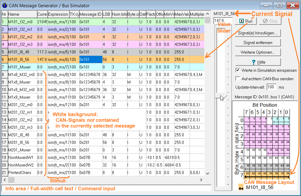
'CAN-Simulator' screenshot (part of the UPT programming tool)
with tabsheet for the CAN signal definition table and 'value slider'.
The CAN message generator can do the opposite: Using the information that you have imported
from a CAN database, it can assemble CAN messages that it can play "into the display simulator".
If the PC is connected to a suitable CAN bus interface, it can even send those messages
to a real hardware.
Extracting CAN signal definitions from UPT variables
The fastest way to simulate all CAN-signals used in your application is to extract their
definition from the application itself (because the 'UPT display variable' definitions
contain all the simulator needs to know for assembling such messages):
- Open the CAN Simulator window: From the tool's main menu, select Tools .. CAN Message Generator / Bus-Simulator
- There: Add signal .. Copy ALL signals from UPT display variables
- Check option Inject values into simulation, and if you promise to be careful, Send on 'real' CAN bus
- Click into the table on the signal you want to 'simulate' (or send), to select the row
- Use the vertical slider (that is now connected to the selected signal) to modify the value
The above method is only the fastest / easiest way to simulate a single signal.
To modify multiple values simultaneously, enter a stimulus (numeric expression) in the
column titled 'Expression (Stimulus)'. The display interpreter will periodically evaluate this expression,
and use the result as new 'physical' value. More on this in a later chapter.
Treatment of UPT variables flagged as 'TX' (Transmit from the simulated device's point of view)
Since the user-programmable display (UPT, e.g. "MKT-View") may optionally transmit CAN signals,
there's a potential problem: If the CAN-simulator would also transmit those variables (as CAN signals),
besides the 'real' UPT connected to the same bus, the result would be a collision of CAN message identifiers (*).
But except for deliberate 'stress tests' (in the lab), transmitting the same CAN message ID from more than a single node
(here: the UPT, e.g. MKT-View, and the CAN-simulator) must be avoided.
Since 2023-01-05, the CAN simulator (integrated in MKT's "CAN Terminal Programming Tools") tries to avoid CAN message identifier
collisions as follows:
- Only CAN-signals that will be RECEIVED by the UPT (through a UPT display variable connected to a CAN-"Receive"-message)
will be flagged for TRANSMISSION in the CAN message generator / bus simulator;
- CAN-signals that will be TRANSMITTED by the UPT (through a UPT display variable connected to a CAN-"Transmit"-message)
will be flagged for RECEIVE-ONLY in the CAN message generator / bus simulator,
and will be marked as "RX" (short for 'Receive-Only') in colum "TX cyle".
The option 'Inject values into simulation'
By default, the option Inject values into simulation is set. This causes the
signal values modified via slider or stimulus (numeric expression) will enter the
simulation within the programming tool, as a replacement for CAN messages
received from the CAN-Bus.
In many cases, this option is already sufficient to test and develop an application
on the PC ("run it inside the PC"). Unlike option 'Send on real CAN bus',
it doesn't affect any external devices connected to the PC. Furthermore, it can be used
without a CAN-bus interface on the PC.
The option 'Send on real CAN bus'
The option Send on real CAN bus should only be used if the PC (with the programming tool)
is directly conntected to the MKT View (or similar DUT, 'device under test') with a suitable
CAN-bus interface, and no other active CAN nodes
are connected to the same network.
In this case, the programming tool sends those messages, which the DUT expects to
receive from a vehicle's control unit or similar. If both (CAN-simulator
and vehicle) were connected simulaneously, this would cause severe collisions on the bus
which must be avoided under any circumstance. If multiple nodes send CAN frames with the same
message identifiers, there will be unresolvable conflicts during the bus arbitration phase,
which sooner or later may cause one of the sending nodes to enter 'Bus-Off' state, i.e. it stops sending.
You don't want to experience this in a vehicle while driving !
The 'Send on real CAN' option also controls the behaviour of the simulator command can_tx()
as explained here (footnote for can_tx).
See also: Recording and playing back messages via 'CAN-Snooper',
Playing back recorded CAN-traffic in the simulator,
The PC's CAN bus interface.
CAN signal definition table
As mentioned in the introduction, signal definitions for the CAN simulator are usually extracted
from the application's variable definitions,
or from the CAN database (if still available).
Alternatively, signal definitions can also be entered manually in a definition table.
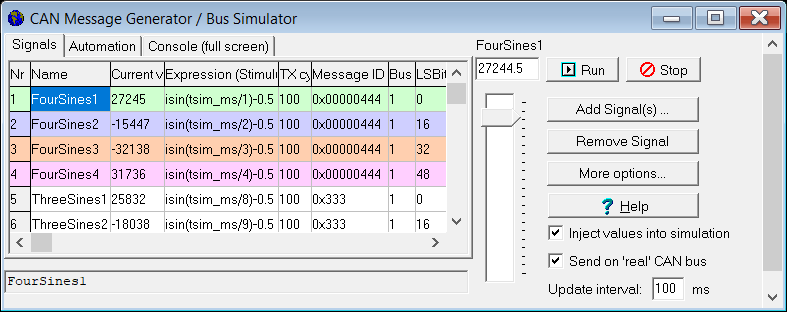
Signal definitions table for the CAN simulator. As usual,
column widths can be adjusted via mouse in the table header.
When selecting a cell, its full text is shown below the table.
Some of the colums in this table (listed below) have the same meaning as described
in the manual about display variables connected to CAN signals.
Details about the "CAN-(Message-)ID", "position of the least significant bit", "Intel / Motorola byte order",
etc can be found in the document linked above.
Name
- Usually copied from the variable definitions table
as explained here.
- Hint about signal names:
- You can launch a global search
for all display variables in the currently loaded application
through the signal definition table's context menu.
Right-click on the name in the grid to open the context menu,
then select 'Global search for XYZ' (where XYZ is the clicked name).
This does not only search the name in the CAN simulation, but also
on all display pages, event definitions, etc, of the loaded application.
Expression (Stimulus)
- Optional 'generator function'. If present (non-empty string), this numeric expression will be periodically
evaluated by the display-interpreter (interval adjustable on the right side).
The result will be copied into the Current Value,
from where it can be mapped into a CAN message.
A double click into an empty cell in this column generates an expression
for a low-frequency sinewave. Each signal will have a slightly different frequency,
and the amplitude will be scaled for the signal's MinValue
and MaxValue. To repeat this for all signals
defined in the table, select 'More..' (button), and menu item 'Generate Stimuli for ALL signals'.
Thus, with very little effort, the simulator can generate ever-changing
"dummy values" for the CAN signals. Example:
isin(tsim_ms) / 4 creates a sine wave
with amplitude 32767/4 = ca. 8191,
period = 1024 milliseconds, i.e. frequency about 1 Hz,
with the first rising zero-crossing
at the start of the CAN-simulation.
(Explanation: The interpreter function tsim_ms delivers
the elapsed time, in milliseconds, since the start of the CAN signal simulation ("Run"-button) as an integer value.
The older function ti_ms (which, unlike tsim_ms, is also
available in the device firmware) delivers the number of milliseconds elapsed since
the display application was launched, or a "simulated target reset" was issued
through the tool's main menu. The isin function
expects an argument range of 0..1023 for a full 360° sine wave cycle,
and delivers an output value range of -32767 to +32767.)
- Note:
- A stimulus may be disabled via command.
In that case, the definition cell will be marked as 'temporarily disabled' with a transparent cross
as explained in chapter 'Automation'.
Current Value
- The signal's current physical value. Can be modified via vertical slider on the right side,
or by entering a suitable stimulus under 'Expression'.
Even without a stimulus, the Current Value may be generated via command
(csim.<SigName>) on the Automation tab.
See also: Signal value stimulus vs. signal value set via command.
TX cycle (ms)
- Transmit cycle for this signal in milliseconds.
Without a cycle (0 ms), a signal will be transmitted immediately after being modified via slider, stimulus,
or command (csim.<SigName>), i.e. "event-driven".
This can cause a huge bus load if many values are modified at the same time (in a single update cycle) !
Via menu item More ... / Set transmit intervals for all signals, you can activate
the periodic transmission of all signals contained in the table with just two mouse-clicks.
For all signals that don't have a transmit-cycle yet, the time (in milliseconds)
will be copied from the edit field in the right half of the window.
CAN signals that have been imported from "to-be-TRANSMITTED" UPT variables will be marked for
RECEPTION ("(RX)") in this column, to avoid CAN message ID collisions as explained here.
Message ID
- Hexadecimal CAN message identifier with prefix '0x'.
Three digits for "standard-IDs" (11 Bit), eight digits for "extended IDs" (29 bit).
- Bus
- Only for systems with two or even more physical CAN interfaces.
So far, only tested with multi-channel Kvaser interfaces like 'Kvaser Hybrid 2xCAN/LIN'.
Bus 1 transmits into the first CAN interface ("CAN1" on the MKT cable, "Ch.1" on the Kvaser interface), etc.
LSB pos
- Position of the signal's least significant bit within the CAN data field (0..63 for "classic" CAN).
Num bits
- Number of data bits occupied by the 'raw' CAN signal (within the CAN data field, max. 64 bits for "classic" CAN).
Byte order
- For historic reasons, 'M'="Motorola" (most significant byte first) or
'I'="Intel" (least significant byte first) ... the annoyance known as 'endianness'.
Data Type
- U=unsigned integer, S=signed integer, F=single precision float, D=double precision float.
Type of the 'raw' value, inside the CAN data field (usually integer; float or double as 'raw signal type' is quite rare).
Factor
- Multiplier for converting the 'raw' CAN value into the physical 'display' value.
Offset
- Will be added when converting the 'raw' CAN value into the physical 'display' value:
Physical value (e.g. Oil Pressure in Bar) = raw_value * Factor + Offset
MinValue, MaxValue
- Possible range for the physical value. In the CAN-simulator, used to scale the
'vertical slider' position into a new physical value: Top = maximum, bottom = minimum.
Multiplexer
- Definition of an optional signal multiplexer, used to squeze more signals into a
CAN message than permitted by the 64-bit data field (for 'classic' CAN).
Details and format (syntax) as explained here.
Since 02/2021, the CAN simulator may indicate a problem ("red cross") if there is a
stimulus (expression) defined for a MULTIPLEXER SIGNAL
(not just a multiPLEXED signal):
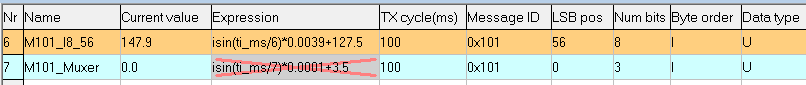
Illegally defined stimulus ("Expression") for a Multiplexer Signal.
In this case, the error indicator (red cross) would disappear by clearing the stimulus.
See also: Peculiarities with the transmission of multiplexed CAN messages.
To quickly add all signals that you need for testing a certain 'display application',
first load the application in the programming tool (so the tool 'knows'
all signals and how to map them into CAN / CAN FD messages),
then switch to the CAN simulator, and click on 'Add Signal(s)' as shown below:
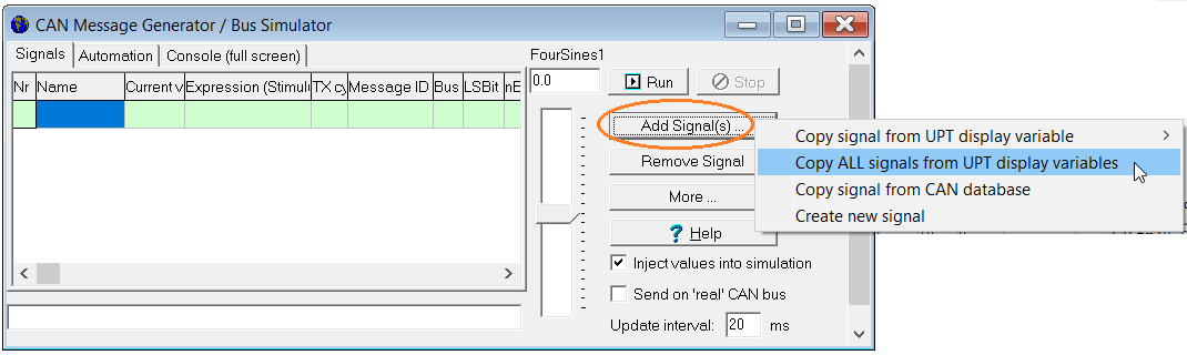
Steps to quickly fill the 'signal definition table' from a loaded UPT display application
Click on "More ..." (button) ...
"Generate stimuli for ALL signals"
to let the program fill out the table with expressions (stimuli) for each signal,
generating sinewaves with amplitudes matching the signal's full range,
and frequencies depending on the signal index (so all signals
will have different values when sent to the bus, or 'injected' into the
simulation).
The content of the definition table can also be exported as a CSV file.
To export the table, select More .. Save definitions as file.
In the same menu, definitions can also be imported (Load definitions from file).
If the exported file with signal definitions still exists during the next session,
it will automatically be loaded when opening the CAN simulator window. The CSV file
has almost the same structure as the visible table.
The CAN Simulator's "Update Interval"
The 'Update Interval' defines the minimum time between two updates of the
CAN signal definition table,
but also the periodic evalation of the Conditional Action table
(explained in a later chapter). Depending on the speed of your PC, the actual updates
of the GUI may require longer than this parameter ... especially with update intervals
below 100 milliseconds, the PC (and/or the Borland VCL-based GUI) may not be able
to keep up the pace. Thus, take the 'Update-Interval' (editable as a value
in milliseconds in the common part of the CAN simulator window) with a grain of salt.
Automation / Programmable test sequences
In many cases, the cyclic transmission / simulation of CAN signals is sufficient
to replace signals from a real network (CAN, etc).
In a few advanced test cases, the CAN simulator additionally has a kind of
'programmable' control itself, quite similar to the programmable
'Event-Definitions' in the UPT display application.
The basic principle is:
-
You define certain "events" (conditions) in a table, and tell the program what to do if
such an event occurs (actions).
(this is quite similar to the "IF"..."THEN"-statement which you may know
from some programming language).
-
The table with these IF's and THEN's is periodically evaluated, for example every 100 milliseconds
(adjustable via the "Update Interval"
in the non-tabbed part of the CAN simulator window).
-
The IF-column (event,condition) in the table of conditional actions can be any numeric expression,
or the call of an interpreter function which returns a numeric or boolean
value. Any non-zero value is treated like the boolean value TRUE.
They are evaluated by the built-in interpreter.
Example: tsim > 10
(the result of this expression is TRUE if the CAN-simulation has been running for 10 seconds or more)
-
The THEN-column (action) in the table can be one or more interpreter commands,
separated by colons.
Example: timer0.start(5) : capture : REM capture the screen as a file when the 1750 Hz tone is detected
In addition, user-defined actions (command lines) can also be invoked "manually" via
three programmable buttons, located in the
upper part of the 'Automation' tab.
Conditional Action table
The "Conditional Actions" are displayed in a table (string grid) on the 'Automation' tab.
The function is similar to display application's event definitions.
Inspired by PLCs (programmable logic controllers), all lines of this simplistic 'program'
are executed once per update cycle.
The definition table for Conditional Actions may look like this:
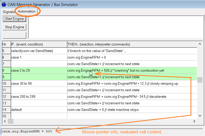
'Conditional Actions' for the CAN simulator (loaded from programs/CANSim_for_SignalMultiplexerTest.csv)
If a cell in the "IF.." column (condition) delivers a nonzero value (logical "TRUE") when being evaluated
by the interpreter, then the cell in the same row under the "THEN.." (action) is executed as a command line.
Both conditions and actions are evaluated/executed by the same interpreter that is also used
for the programmable display application. To use this interpreter for the
CAN simulator without interfering with the display application, it has been extended with a
few simulator-specific functions and commandss that will be presented later in this document.
For example, the CAN simulator's "interpreter stub" (invoked on module prefix csim)
allows accessing the simulator's timebase (tsim),
extra timers (csim.t0 .. t9),
extra variables (csim.var.<VarName>), and so on.
All conditions that are momentarily TRUE will be marked
with a green background in the corresponding cells (in the "IF"-column).
If an error occurrs when evaluating a condition or action, the cell will have a red background,
and the status line (below the table) will show details about the error.
A yellow background in the first column (with the line numbers) means
'a breakpoint in this line has fired, and paused the execution' or 'this line is the next, waiting for execution in single-step mode'.
More about breakpoints and single-stepping follows in a later chapter.
The entire Conditional Actions ("CA") table is evaluated / executed
in a single over (unless debugging in 'single step' mode).
The CA table is used to implement state machines. It is not a replacement for a full-grown scripting language.
Typical use cases are:
- Generate 'special' signal values that would be too difficult for a single-line stimulus
(use csim.<SigName> for that purpose)
- Implement a test schedule ('Fahrplan'), using tsim,
tsim_sec, or one of the CAN simulator's extra timers
to control transmitted values
To modify the sequence of conditions and actions in the table, you can simply grab
the 'Nr' cell you want to move with the left mouse button, and -while keeping the
button pressed- move it up or down to the new destination. While dragging items,
the grid (visual table) marks the new location (row) by a bold horizontal line.
To inspect the current value of variables or certain expressions in the CA table,
simply point the mouse over it (without clicking). If the interpreter can evaluate
the 'word' (delimited by spaces or other special characters) under the mouse,
the result will be displayed in the info field below the table.
To undo the last 'cell editing' operation, press the ESCAPE key while the keyboard focus
is on the string grid. Pressing ESCAPE a second time will 'redo' the 'undo' operation.
'select'..'case'..'endselect'-blocks in the Conditional Action table
Besides as simple "IF.."/"THEN.." lines, the conditions (table column labelled 'IF..') can be
used to implement a select-case-default-endselect block as in this example:
Similar as the select..endselect statement in the script language,
the CAN simulator's case and default labels don't "fall through" from one case to the next,
so there is no need for a 'break'-statement after each case. Also note the CAN simulator's 'select'/'endselect'
uses default:, not else, to avoid misinterpreting them.
- select( <selectValue> )
Stores the value in an internal buffer, from where it will be compared with all 'case' values
in all lines until the matching endselect.
- case <caseValue> :
Lets the "program" execute the current line, and lines with an empty condition that follow immediately,
if the case-value equals the value stored internally by select ('<selectValue>').
The colon after the case-value is optional.
- case <fromValue> to <toValue> :
Almost the same as the 'simple case', but compares the value stored by select
against an entire range of values. As a condition, evaluates to TRUE if selectValue
(the value stored by select) is larger or equal to fromValue,
and less or equal toValue.
- default :
Lets the "program" execute the current line, and lines with an empty condition that follow immediately,
if the select-Value (the value stored by select)
matches none of the case-values
or case..to-ranges between the lines with the 'select' and the 'default:'.
Like the colon after 'case' values, the colon after the 'default'-label is optional.
- endselect
Ends a block with 'select', 'case', and optional 'default' labels.
After a matching 'case' or executing the instructions after a 'default', of if the select-value doesn't match any 'case'
and there's no 'default' at all, the program jumps into the line after the 'endselect'.
Note: At the time of this writing, the CAN simulator's select-endselect only supported numeric values. Floating point is ok.
It cannot be used to branch by string values.
In contrast to the "C" programming language and the display's script language,
case-values don't need to be constants - but they usually are.
Special interpreter functions for the CAN Simulator
In many cases, the 'Conditions' (events) will be simple comparisons
as shown in the previous chapter (e.g. tsim > 10).
The following special interpreter functions have been implemented
especially for the IF-column (condition, event) in the CA table:
- initialising
This flag is TRUE (one) once when initialising the program, or after loading
a new configuration from a *.csv file. It is typically used to set variables
to their initial values.
- always
is simply ALWAYS true. The action (command line) in this row will be executed
in every update cycle.
- never
is the counterpart to the 'always'-event - it is just 'never' true (boolean
'false', or numeric value zero). You may as well enter a zero in the IF'-column
of the conditional actions, but 'never' is a bit more descriptive.
As strange as it seems, the 'never'-event is not completely useless:
It can be used to add comments in the table, to describe
(in a single line) what the following part of the program is supposed to do.
The action for such a line typically begins with the interpreter command
REM (remark) or (C++ style) with a double forward slash.
- else
Returns TRUE if the condition in the previous line was FALSE; and FALSE if
the condition in the previous line was TRUE. Use this to do "something" in
a certain line #N, and do "something else" in line #N+1 if the condition
in line N is not true. See the examples at the end of this chapter.
Note: If there is no condition in a certain line of the
CA table (empty "IF.."-cell),
the 'empty' condition cell evaluates to TRUE if the condition in the previous line was TRUE;
and FALSE if the condition in the previous line was also FALSE.
- sometimes
Congratulations, you read the documentation carefully enough to spot this easter egg.
Guess how often this function returns TRUE when used as a condition.
- csim.tsim, tsim
Returns the current 'CAN simulation time' as a floating point value in seconds.
For read-access, the module prefix "csim." can be omitted.
This timer starts at zero when clicking the 'Run'-buttons, and is often used
to compute 'running' signal values, e.g.
csim.sig.DrivenPath_km := tsim * (50.0/3.6) // driving at 50 km/h
For special cases (e.g. to simulate a 'time warp'), csim.tsim can be set
to any value via assignment.
- csim.t0 .. t9
Checks if one of the CAN simulator's ten user timers is expired
or has reached the end of a period, after being started via csim.ts ("timer start").
A full example showing how to start and poll these timers can be found here.
There are similar timers in the interpreter 'outside' the CAN simulator
(t0 .. t3), but to avoid
interference with the display application, only use the CAN simulator's timers in the CA table.
- csim.tv0 .. tv9
Reads the current timer value of a CAN-simulator timer.
The time starts at zero [seconds] when a timer was started (e.g. csim.ts0(12.3)),
and runs up to the timer's period (in this example, 12.3 seconds).
At that time, a single-shot timer would stop, and a periodic timer
would wrap around from the period time to zero. Thus, for periodic
timers, csim.tv generates a sawtooth function.
- select, case, default, endselect :
Explained in another chapter.
Reminder: A function returns a value to the caller, and thus can be used
as part of a numeric expression or, in this context, a condition.
A command (or procedure) as listed in the next chapter does not, and thus
cannot be used as part of an expression. But a command may be part of ..err..
a command line or, in this context, an action.
Check for CAN reception via can_rx(<ID> <data field>)
The interpreter function can_rx checks if since the last call,
a CAN message with a certain message identifier or/and a certain data field
('payload') has been received.
The syntax is similar as in the author's 'CAN Tester for Windows', and matches
the format of the simulator's can_tx() command (which can
inject CAN messages into the simulation, but also send messages on a 'real'
CAN bus interface).
The length of the data field (in bytes) is automatically detected from the content
of the data field (which may contain "xx" as placeholder for data bytes with
'any value' accepted for filtering).
Intended to be used as 'condition' in the simulator's 'Conditional Actions'
on the 'Automation' tab, can_rx() [when invoked with an argument list in
parentheses but nothing after that] returns 1 = TRUE if a matching
message was received since the previous call, or 0 = FALSE = "no matching
CAN reception".
Examples :
can_rx( 0x123 00 11 22 33 44 55 66 77 )
   checks if since the last call from the same line in the 'conditional actions',
   a CAN message with hexadecimal message identifier 0x123,
   and an eight-byte data field 00 11 22 33 44 55 66 77
   has been received.

can_rx( 0x123 FF xx xx )
   checks if since the last call (.. see above ..), a CAN message
   with a three-byte datafield, with the first data byte containing 0xFF,
   has been received (with xx = "don't care" for the 2nd and 3rd byte).
Special interpreter commands for the CAN Simulator
Besides the interpreter's standard commands, the following special interpreter commands (and a few functions)
have been implemented especially for the THEN-column ("actions") in the CA table:
- csim.stop
Stops the periodic evaluation of the 'Conditional Actions'
and the transmission of CAN messages assembled from
signals defined on the CAN simulator's signal definition table.
- csim.<SigName> or csim.sig.<SigName>
Allows read- and write access to the Current Value
with a matching (signal- or variable-)name in the signal definition table.
Example (where "ThreeSines1" is the name of a signal or variable):
| Nr | IF.. (Condition) | THEN.. (Action) |
|---|
| 1 | tsim < 10 | csim.ThreeSines1 := tsim |
Even if there was a stimulus for signal "ThreeSines1"
delivering a sinewave, the example generates a rising 'ramp' for the signal during the first 10 seconds.
As long as the Current Value is set
via interpreter command, it will not be taken from the stimulus in the same update cycle.
As soon as a signal is not set via command in the CA table anymore,
its 'value' will be taken from the stimulus again (unless the stimulus was
disabled via command).
If the signal name collides with one of the keywords
or components after "csim.", the collision can be resolved by using csim.sig.<Signal-Name>.value
instead of just csim.<Signal-Name> .
- Note:
- In many cases, the simulator's CAN signal table has been extracted
from a display variables (details here).
Since the simulator uses the same interpreter as the display application itself,
the interpreter (invoked from the 'Conditional Actions' to evaluate
conditions or execute actions) can access both
- the display variable fed from the 'decoded' received signal,
and the CAN simulator signal from which the value was sent.
Thus, the CA table can also compare the 'transmitted' signal value
with the 'received' signal on the other end (mapped into a UPT display variable).
See also: Details about command-driven signal transmission,
csim.sig.<SigName>.tx_flag ("forced" transmission
even if the value didn't change and there's no periodic transmission).
csim.<VarName> or csim.var.<VarName>
Allows read- and write access to a user-defined variable within the CAN simulator.
In contrast to signals, these variables
are not mapped into CAN messages, PDUs, etc, so they don't "communicate" directly with a network.
These variables simply begin to exist by assigning a value to them (no extra declaration required).
The first assignment usually happens in the CAN simulator's
Conditional Actions table
in one or multiple lines with condition = initialising,
which is where all simulator-internal variables (not CAN signals) should
be initialized. See the 'timer'-example further below.
If the variable name (<VarName>) doesn't clash with signal names
or other 'csim.'-commands/functions, you can use the short form
(csim.<VarName> instead of csim.var.<VarName>).
csim.btn[N].caption (with N = 0..2 for three buttons)
Reads or writes the 'Caption' (text) shown on one of the three programmable buttons.
As usual (in "C"), the array index in squared brackets is zero-based.
csim.ts0(<interval in seconds>) .. csim.ts9(..)
Starts one of the ten CAN simulator timers for a given time in seconds in single shot mode (not periodic).
After the interval expires, the matching function csim.t0 .. t9
will return TRUE, until your CAN simulator script resets the 'expired'-flag via csim.tr0 .. tr9.
If an already running single-shot timer is restarted (same start command issued twice) before it expired,
the full interval starts again (note the difference to periodic timers which won't restart).
That way, a single-shot timer can be used as a watchdog: As long as it is re-started frequently,
it's timer event (e.g. csim.t0) will not fire.
csim.ts0(period,pulse-time) .. csim.ts9(..)
Starts one of the ten CAN simulator timers for a given time in seconds in periodic mode (aka 'pulse generator').
Every period begins with the 'pulse low time', and ends with the 'pulse high time'.
The timer-event polling function, csim.t0 .. t9
will return TRUE only ONCE in a period, approximately <pulse-time> seconds before
the end of a full period (at the pulse's low-to-high transition).
If an already running periodic timer is restarted with the same parameters (same start-command issued twice),
it simply keeps running without causing a phase glitch (note the difference to single-shot timers which really would restart).
Example demonstrating the use of timers, signals, and variables:
- Line 2 starts the CAN-simulator's first user-timer in periodic mode,
with a period of 1.5 seconds, and a pulse-high-time of 0.5 seconds during each period,
beginning 10 seconds after starting the CAN simulation.
- Line 3 polls (and "consumes") events from the first timer,
and increments a self-defined simulator variable ("MyCounter") in each timer period.
- Line 4 copies the "value" of a timer itself (counting up in seconds) into one of the
signals (defined on the tab), but only if that timer is currently running.
This generates a ramp function beginning at zero when the timer was started,
regardless of the stimulus for that signal.
- Notes:
- If period- or pulse times are shorter than the CAN simulator's adjustable update interval,
you may miss events from that timer in the CA table,
and the counter used in the above example ("MyCounter") won't increment as fast as it should.
The post-increment (++) and
post-decrement (--) operators may appear familiar from "C",
but here they are only available for variables and signals
inside the CAN simulator. They only work in
command lines (where values are writeable), but not in
numeric expressions (where everything is read-only).
csim.tr0 .. tr9
Resets the specified timer's 'expired' flags. Typically invoked
from the Conditional Actions after a certain timer has expired,
possibly and-combined with other conditions, e.g.
csim.print(value1,value2,...)
Prints a list of values into the 'text log' on the simulator's "Automation" tab (above the conditional action table).
Values may be integer, floating point, strings, or expressions generating any of these types.
Numeric values are printed as decimal strings.
If values are separated by comma, a space character is emitted as a separator instead.
If values are separated by semicolon, no space character is emitted.
Example:
csim.print("Peak brake pressure:",csim.var.MaxPressure,"bar")
The 'print' command can optionally modify the colours used on the text console.
If the first function argument is a colour, it's the text colour (aka foreground colour).
If the second argument is also one of the colour names listed here,
then the 2nd argument defines the background colour. Examples:
csim.print(clRed, "No response from device under test !")

csim.print(clWhite, clGreen, "Test finished, no errors.")
Like 'writeln' (write line) in Pascal, csim.print appends a
Carriage Return and New Line character after the text, to enter
the next line for the next call.
csim.write(value1,value2,...)
Almost identical to csim.print, but 'write' does not
automatically wrap to the next line after the 'printed' text.
Thus, subsequent calls of csim.write can write into a
single line.
csim.tscreen.xyz
Special commands to control the 'text screen' / Text Console.
Accessing CAN signals, internal variables, and 'programmable' timers
The Conditional Actions typically modifies a few CAN signal values (accessed by their names)
which the simulator will map into CAN messages (or similar containers), just as if their values
have been taken from a stimulus. Examples for this have already been presented in the previous chapter.
The interpreter can also access (read and write) self-defined internal variables
that only exist within the CAN simulator.
Last not least, the interpreter also has a few programmable timers that can be used to generate
certain waveforms (peridic timers) or act like a timeout monitor (single-shot, "retriggerable" timers).
Most of the commands and functions to access those objects have already been listed in this chapter.
The subchapters below provide more details, but are not necessary for simple test applications.
Details about command-driven signal transmission
This subchapter describes details and extensions for the csim.<SigName> command.
The assignent can be used in the long form, setting e.g.
csim.sig.EngineRPM.value := 2300
or in the short form without the optional ".sig" and ".value" tokens:
csim.sig.EngineRPM := 2300
in the Conditional Action table
assigns a new value (here: 2300 RPM) to the signal (here: "EngineRPM").
Even if there was a stimulus for this signal, the assignment
via command overrides the value from the stimulus for the current update cycle
(remember, the Condition Actions work like a PLC, where all outputs are sent
to the "outside world" at the end of a PLC cycle.
With rare exceptions (*), signals and their
containers like CAN-messages are only sent once in an update cycle).
Whatever remains at the end of an update cycle (set via command, stimulus unless disabled, or "value slider")
will be sent once per cycle or not at all - depending on the
signal's individually adjustable Transmit cycle (TX cycle in milliseconds).
A signal stimulus can also be disabled or re-enabled for more than one update cycle via command, e.g.
csim.sig.EngineRPM.enable_stimulus := 0 // disable signal stimulus
csim.sig.EngineRPM.enable_stimulus := 1 // enable signal stimulus
Stimuli that have been permanently disabled via command (enable_stimulus=0)
will be marked with a blue cross in the signal definiton table.
Stimuli that are temporarily disabled by assigning a signal value via command
will be marked with a green cross.
The next subchapter explains how the simulator's update cycle,
a signal's transmit cycle,
the interpreter's csim.sig. command, and the actual
transmission of CAN messages (or similar containers) affect each other,
and how you can force transmission of a signal (along with its container)
even if the value is unchanged, and regardless of the "scheduled" TX cyle.
Command-driven signal transmit timing
Simply modifying a signal's current value as shown in the example above
will not immediately map it into its 'container' (CAN message, PDU, etc).
Instead, if a non-zero transmit cycle has been defined for the signal in the
signal definition table, it may take
up to one 'TX cycle' until the new value is emitted to the network.
As specified for the 'TX cycle', a cycle time of zero
means the signal is event-driven. Event-driven signals will be sent as soon
as all Conditional Actions have been evaluated. At this point,
the CAN simulator compares all signal values from the current update cycle
with the 'old' values from the previous update cycle.
All signals with a now different value will automatically be marked
as 'pending for transmission'. Later, after mapping all all signals
into their transport container, the 'TX-pending' flags
are checked and cleared as soon as the container has been sent (or injected
into the simulated display applicaion). This is the last step of the
CAN simulator's update cycle.
In most cases, signals are transmitted periodically, and it doesn't matter
how frequently they really arrive at the receiver (with pure CAN, the 'arrival'
of a certain message at all intended receivers cannot be guaranteed anyway).
You just provide signals like "EngineRPM", "VehicleSpeed", "OilPressure", etc,
and if a single CAN message gets lost on the way, the intended receiver
will hopefully get the next one (in the next signal transmit cycle).
In other cases, signals are not transmitted periodically but event driven
as already mentioned in the introduction. This is easy - you just set the signal's
transmit cycle to zero, and the simulator will only send it if the value is different
from the previous update cycle.
In rare cases, you may want a signal to be transmitted both periodically and event-driven.
Simply assigning a different value via command
will not cause an immediate transmission if the transmit cycle is nonzero,
because that would make the code in the 'Conditional Actions' unnecessarily complex for most test cases.
For that purpose, the interpreter may force (erzwingen) signal transmission regardless of the
signal's transmission cycle, and regardless of the signal value being different (from the
previous update cyle or not) as follows:
- In your Conditional Actions, set the signal value itself, e.g.:
csim.sig.EngineRPM.value := 2300
- In your Conditional Actions, also set the signal's "transmit flag" via command, e.g.:
csim.sig.EngineRPM.tx_flag := 1
This will cause the simulator to map this signal into its container (e.g. CAN message),
even if the value is still the same as in the previous update cycle,
and even if the signal's individual transmission timer hasn't expired yet.
The transmit-flag will be automatically cleared after transmission of the container.
Transmission of multiplexed messages
Depending on their transmit interval, signals defined with a multiplexer
may exhibit some unexpected behaviour when sent by the CAN simulator:
- If the CAN message (aka CAN frame with a certain message-ID) contains non-multiplexed
("normal") signals besides multiplexed signals, those non-multiplexed signals
may be sent more often than intended. For example, assume "NonMuxedSignal" is a non-multiplexed
signal that you want to send only once per second, and "MuxedSignal1" and "MuxedSignal2"
are multiplexed signal (mapped into the same CAN message), periodically sent every
100 milliseconds. It is technically impossible
to send a message without the non-multiplexed signal. Thus, whenever sending
a message with "MuxedSignal1" or "MuxedSignal2", the current value of "NonMuxedSignal"
will also be contained in the message frame. The actual transmit period of
"NonMuxedSignal" will be 100 instead of the intended (configured) 1000 milliseconds.
- If a CAN message contains multiplexed signals (plural) with different
multiplexer values, and more than one of these signals are "waiting for transmission"
(tx_flag set via command or automatically), the CAN simulator
will send multiple CAN messages with the same message-ID but different multiplexer value
within fractions of a millisecond (if CAN bitrate and CAN driver permits).
This may cause a problem in certain receivers, most noteably in small microcontrollers
without a sufficiently large hardware- or interrupt-driven receive buffer.
Direct transmission / "injection" of CAN messages via can_tx(<ID> <data field>)
The simulator's interpreter command can_tx can be used to send simple CAN messages,
without assembling the message data from signals (see previous chapter).
Instead, the can_tx command expects the to-be-transmitted CAN message identifier, followed
by the to-be-transmitted data field, in the parameter list in parentheses.
The length of the data field does not need to be explicity specified
(the number of bytes to send is simply counted from data field).
Examples :
can_tx( 0x123 00 11 22 33 44 55 66 77 )
    "Sends"(*) a CAN message with the hexadecimal 11-bit ID 0x123,
    and the hexadecimal 8-byte data field 00 11 22 33 44 55 66 77,
    or (if the option 'Send on reak CAN bus' isn't set)
    only injects this message into the device simulation that currently runs in the programming tool
    (to replace a message transmitted from an ECU or similar external device).

can_tx( 0xABCDEF.x 01 02 03 04 05 06 )
    "Sends"(*) a CAN message with 29-Bit message ID 0x00ABCDEF (.x = "Extended"),
    and the specified data field (also hexadecimal per default).
The CAN-simulator's "can_tx()" command uses the same parser as the
ctx()-command implemented in certain
programmable devices (e.g. MKT-View "without CANopen").
Since both commands invoke the same parser, can_tx() can also send the content
of any interpreter variable as part of the CAN message data field,
including a conversion into the data types specified here
(e.g. ".il" = "Intel-Long", ".mw" = "Motorola-Word", ... ).
The can_tx() command only "sends" on a 'real' CAN bus
if the option 'Send on reak CAN bus' is set on the CAN-simulator's
Signals tab. Without this option, can_tx()
only injects these messages (which "would have been sent" by the simulated ECU)
into the device simulation that runs inside the programming tool.
Breakpoints and single-stepping through the Conditional Actions
For hardcore debugging, breakpoints can be set in any line of the Conditional Actions.
If the condition in a line with a breakpoint gets TRUE, the breakpoint 'fires',
causing the periodic evaluation of the CA table, and the periodic evaluation
of stimuli in the Signal Definition to pause. This 'pause' begins
exacly between the evaluation of the condition and the execution of the
action in the same table row.
This gives the developer a chance to inspect 'what is going on', e.g. immediately
before a CAN signal was set to a certain value (via csim.<SigName>">command).
To set a breakpoint on a certain line in the CA table, click into the line on the
fixed column titled 'Nr', and (in the context menu) select 'Toggle breakpoint in line X'.
This can be done at any time, regardless of the CAN simulator running or not.
Later, if a breakpoint 'fires', the simulation pauses in single-step mode.
The line waiting for execution (of the programmed action) is marked yellow,
and the simulation pauses in single-step mode. In that state, press F11
(with the keyboard focus on the CA table) to single-step into the next (yellow) line,
or resume normal operation by clicking "Run". After being paused by a breakpoint,
"Run" will not 're-initialize' the simulation, e.g. this will not
set the initialising flag.
See also ("related subject"): Options to synchronize display application and CAN Simulator.
Programmable Buttons (on the CAN simulator's "Automation" tab)
The three buttons on the upper part of the 'Automation' tab are freely programmable.
They can be used to invoke any sequence of interpreter commands, similar as the commands
used in the Conditional Action's 'action' column.
Whenever the operator clicks on the button (using the left mouse button),
the programmable 'OnClick' handler (command) is invoked.
Clicking on a programmable button with the right mouse button,
or (for touchsceen users) holding the shift key pressed while clicking the button
opens a popup menu as shown below, with choices to modify / edit the button:
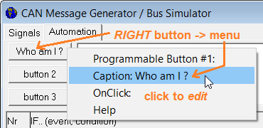
Screenshot of the CAN simulator's "Programmable Button" context menu
The 'Caption' (text displayed on a button) can not only be edited manually, but also
modified via command csim.btn[0..2].caption.
The 'OnClick' handler (string of commands executed on a normal mouse click) may be any
sequence of colon-separated interpreter commands, just like the commands entered in the
'Conditional Actions' "THEN.."-column (action), for example:
The "programming" of these buttons (Caption and command line for the "OnClick"-handler)
are stored as part of the CAN Simulator's configuration (*.csv file).
This way, the entire test configuration can easily be passed on to the customer
as a file (along with the 'display application' in the *.cvt file).
Text Console (text screen showing output from 'csim.print')
During a test run, output generated via command csim.print
will be displayed on a multi-line 'console' (text editor) on the Automation tab,
or (larger display) on the 'Console' tab:
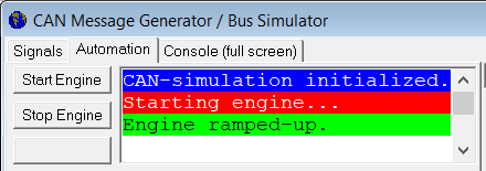
Screenshot of the CAN simulator's 'Text Console'
with deliberately exaggerated use of colours.
Lines of text, or the entire text can be copied from the console
and pasted into a user's own documentation as 'Rich Text' (including colour attributes).
The console window was initially limited to 100 lines of text with up to 128 characters per line.
If a test application 'prints' or 'writes'
more lines into the console than the buffer permits, the existing
text is scrolled up, and the topmost (oldest) line disappears.
The current 'output cursor' position can be accessed as zero-based text coordinate
in csim.tscreen.cx (current column) and csim.tscreen.cy (current row).
The constants csim.tscreen.width and csim.tscreen.height retrieve
the screen buffer size in 'characters per line' (128 ?) and 'number of text lines' (100 ?).
Because the 'console' is in fact a RichText edit control, the colours (especially
for the background) are limited. Thus, when assigning colours to
csim.tscreen.fc (foreground colour) and csim.tscreen.bc (background colour),
or when passing colours to csim.print as function arguments,
only use the following symbolic colour constants:
| clBlack | clWhite | clRed | clGreen | clBlue |
| clCyan | clMagenta | clYellow | clDkGray | clLtGray |
Per default (without explicitly setting colours), text is printed 'black on white'
into the console. The csim.tscreen.cls command erases the
entire console by filling the buffer with space characters, using the background colour
assigned to csim.tscreen.bc before invoking csim.tscreen.cls. Last not least,
csim.tscreen.fill(x1,y1,x2,y2," ") fills a rectangular
text area with the specified character (in this example, with space characters).
Both commands for output to the console (csim.print
and csim.write) support the control characters and
a few HTML-like tags listed further below. The difference between 'print' and 'write'
is the automatic appending of 'carriage return' ("\r") and 'new line' ("\n") after the
output from print (which also clears the 'rest' of the line, which write
does not).
Control characters and -sequences in strings written or printed to the text console:
- "\r" : Carriage Return (ASCII #13). Sets the
text output cursor to the begin of the current line, e.g. does
not enter a new line.
This control character can be used to update text in the current line,
without adding new lines on the console. Example to overwrite
the text in the current line (may be invoked multiple times):
- "\n" : New Line (ASCII #10). Sets the text output cursor into
the begin of the next line. For historic reasons, sometimes appended
after the Carriage Return character.
- "<b>Bold Text</b>",
- "<i>Italic Text</i>",
- "<u>Unterlined Text</u>":
HTML-like start- and end-tags to emit bold, italic, and/or underlined text.
Similar as in the display interpreter's format string
(and in contrast to 'real' HTML), these sequences may be used in any combination or sequence
(HTML requires carefully balanced start- and end-tags; we don't).
Options to synchronize display application and CAN Simulator
The CAN simulator's 'More ...' button opens a menu with the following options
for the synchronisation and interaction between display application (running in the
programming tool's integrated firmware) and the CAN simulator:
- RUN-button not only starts/resumes the CAN simulator, but also the display application:
This option also applies to applies to resuming the display application,
after e.g. being paused when hitting a breakpoint in the script. In this case,
'RUN' doesn't perform a restart/reset, but continues execution of both (display application
and CAN simulation) exactly at the points where they had been paused before.
- STOP-button not only pauses the CAN simulator, but also the display application:
Allows temporarily pausing both, the CAN simulator as well as the
display application (running in the programming tool's device simulator),
almost simultaneously.
- Breakpoints in the display application also stop the CAN simulator:
If this option is set (checked in the menu), the CAN simulation (including the
periodic evaluation of Conditional Actions) will pause immediately when the
user application (running in the programming tool's device simulator) hits
a breakpoint. For example, when debugging a script, you may have set a
breakpoint in a CAN-Receive-Handler in a script.
If the CAN simulator wouldn't stop when hitting that breakpoint, it would
keep sending CAN frames 'into the blue', and the CAN RX handler wouldn't have
a chance to process them.
... This chapter has not been translated yet.
If possible, use the german original,
or an automatic translation of the online version.
