

Contents
- Introduction, Notes about CAN / CAN FD support
- Checking CAN FD capable ports in the programming tool
- Configuring CAN FD capable ports in the device's own System Menu
- How to check the 'realized' CAN FD bit timing
- CAN FD bit timing examples
- CAN FD support in the CAN Logger / CAN Snooper
Introduction, Notes about CAN / CAN FD support
So far (2026), only the MKT-View V (a successor of the MKT-View III and MKT-View IV)
supported CAN FD. Its CPU (an STM32H745) has two internal, CAN FD capable controllers.
Two optional extra CAN / CAN FD controllers (MCP2518FD, connected via SPI)
can be populated on the board, but their maximum bus load is not as high
as the two on-chip CAN FD ports.
In 2026, the MKT-View V finally entered 'production'. New CAN FD related features
are gradually added to the firmware.
Properties of the new devices (beginning with MKT-View V) concerning CAN-FD:
- Four CAN interfaces, usable for CAN as well as CAN FD
- Due to the transceiver hardware, maximum bitrate 4 MBit/sec for CAN FD; 1 MBit/sec for CAN
- Due to the connection between "CAN3", "CAN4" and the CPU via SPI (internal serial interface),
lower maximum throughput than on "CAN1" and "CAN2".
- up to 8 bytes per message for CAN, up to 64 bytes per message for CAN FD
- ideally two times faster than their predecessors (MKT-View III / IV),
if the semiconductor manufacturer's "advertised" 480 MHz core clock become reality;
or three times faster than MKT-View III / IV, if another manufacturer's
Cortex-M7 with 600 MHz clock, CAN FD, and integrated display controller 'wins the race'.
(That 'alternative' CPU was just too bugged to be useful, thus the project
was abandoned after the prototype / evaluation phase).
- Concerning programming, and script language,
the MKT-View V is compatible with MKT-View II / III / IV.
See also:
Configuration of the PC's CAN(/CAN-FD) interface,
Selection of the 'flexible' (high) Bitrate for CAN FD,
Data type tCAN_FD_msg (with 64-byte data field) in the script language,
'Feature Matrix' with similar programmable displays with CAN bus interface(s).
Checking CAN FD capable ports in the programming tool
The device profile (saved along with the application) contains a list of CAN ports that
are 'principally' capable of CAN FD. The "list" is actually a bitwise combination,
where bit 0 represents the 'CAN FD capability' of "CAN1", bit 1 represents "CAN2", etc.
The current setting can be checked in the programming tool on the Settings tab,
under Terminal constants, settings, non-volatile values.
In the table, scroll down to CAN FD capable ports. The value shown in the
right columns shows all CAN ports that are principally suited for CAN FD,
even though the programming tool doesn't know which transceiver (chip) is actually
populated on the board:
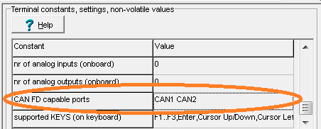
Checking the list of the device's CAN FD capable ports in the programming tool.
(this is for devices not populated with the controllers for "CAN3" and "CAN4")
If re-selecting the device / display doesn't
properly update the list of FD-capable ports, you can fix it manually by clicking
into the table shown above (cell showing "none" / "keine" / "CAN1", etc).
The programming tool will prompt you with a numeric input dialog, where the
bitwise combined value can be entered in decimal notation:
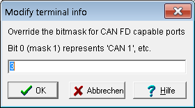
Modifying the list of 'CAN FD capable ports' in the programming tool.
This constant originates from the tool's built-in device database,
and may need to be modified as explained below, e.g. when migrating
from an MKT-View III (not FD capable) to an FD-capable MKT-View V .
Each bit in the decimal value represents one of up to four CAN ports.
Bit 0 (mask 1) represents "CAN FD support on CAN1",
Bit 1 (mask 2) represents "CAN FD support on CAN2",
Bit 2 (mask 4) represents "CAN FD support on CAN3" - even though there's no such hardware yet,
Bit 3 (mask 8) represents "CAN FD support on CAN4" - if there will ever be a controller with FOUR CAN FD interfaces.
The programming tool only allows configuring the
flexible data rate (CAN FD speed after the "bitrate switch")
for all ports that it thinks are CAN FD capable, i.e. with the
corresponding bit set in the parameter shown above.
The Simulation in the programming tool allows transmitting
CAN FD frames (with up to 64 data bytes) only on FD capable ports,
according to the device profile - regardless of the
PC's CAN interface supporting CAN FD or not.
In newer CAN FD capable devices like MKT-View V, you can check or modify the CAN (-FD) parameters as follows,
without the use of the programming tool:
- Simultaneously press function keys F2 + F3 to enter the System menu
- Scroll down (using e.g. the rotary encoder) to User Settings and invoke that menu item by pression ENTER (or the encoder's pushbutton).
- In the 'User Settings', scroll down to more CAN / CAN FD settings.. and invoke that menu item.
Due to the limited space on some displays, the menu items for the CAN bus parameters are quite short,
thus their meanings...
- Baudrate
- For CAN FD, this is the baudrate (in kbit/second aka "kBaud") for the ARBITRATION PHASE.
- Sample Point
- For CAN FD, this is the sample point (in percent) for the ARBITRATION PHASE.
- SyncJumpWidth
- Synchronisation Jump Width for the ARBITRATION PHASE, and (if realisable) also for the DATA PHASE.
May be set to ZERO (or even negative) to let the CAN driver use "good defaults" (hardware specific).
- FlexDataRate
- Baudrate (in kbit/second) used after an optional "bitrate switch" for CAN FD.
Targets with an 80 MHz clock source for the CAN FD controller (as used in the MKT-View V) support:
1000, 2000, 4000, 5000, and (if the hardware and CAN cables permit) 8000 kbit/second.
Please consult your device's hardware manual for details.
- DataSamplePt
- For CAN FD, this is the sample point (in percent) for the DATA PHASE (i.e. used after an optional "bitrate switch").
Depending on the CAN FD controller clock, only a few sample points can be realized.
In other terms: What you enter in this field may be just a "wish" - see details further below.
Set this field to ZERO to use the recommendation by CiA (CAN in Automation), "approximately 80 %" or slightly less.
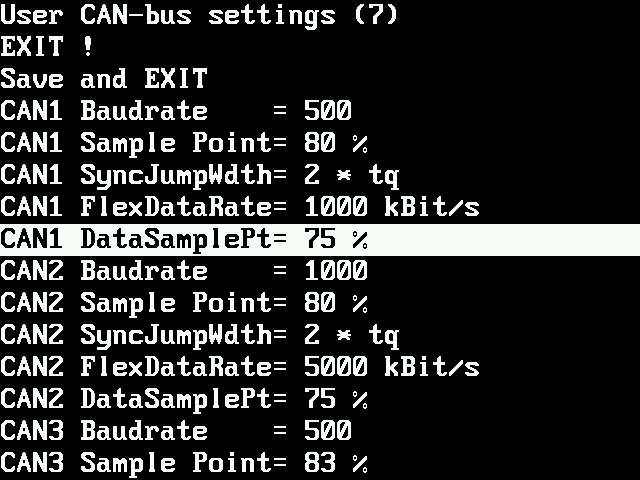
Screenshot of the CAN bus settings in an experimental firmware for the MKT-View V (2026-08-05)
How to check the 'realized' CAN FD bit timing
As explained in the CAN FD bit timing examples,
the configurable "Sample Point" (in percent) is just a "wish". Depending on the
CAN controller clock, and the bitrate (especially high bitrates in the DATA PHASE),
the realizeable sampling point may be different than what had been selected in the programming tool,
or entered in the numeric input fields in the System Menu.
- Technical background:
The programming tool does not know the target's controller clock, and the architecture
of the bit CAN controllers timing registers, requirements for prescaler, etc,
so the tool does not know the width of a single "tq" (time quantum) in nanoseconds,
and thus cannot determine the 'stepwidth' (granularity) of the sampling point.
Devices equipped with a 'real' USB interface and support for MTP (Media Transfer Protocol)
can generate a CAN bus 'status report' in the form of a simple text file.
To retrieve that from the device, connect the USB to e.g. a Windows PC, open the 'Windows Explorer'
(former, less ambiguous name was 'File Explorer'), and try to locate the device's MTP server
in the tree on the left side. For an MKT-View V, the name will be "MKT-View V MTP".
Expand the subnodes of that tree, to see the storage media accessable inside the MKT-View.
The storage device named "system" contains placeholders for various files "generated on-the-fly"
(in the moment you read them via MTP). One of those files is /system/can_bus_status.txt,
with the following content (example with just a tiny fragment):
File: /system/can_bus_status.txt
Created: 2026-08-06 08:25:46 by  MKT-View V / CAN FD

CAN1: 500 kbps, SJW=1, tq= 25.0 ns, SamplePt=82 %      ('Sync Jump Width' and bit timing used for the
                                                           'Arbitration phase' or for 'classic CAN')
      Data Phase: 5000 kbps, tq=12.5 ns, SamplePt=75 %    (bit timing used after CAN FD's optional
                                                           "bitrate switch", in the DATA PHASE)
      Counters: RX=0, TX=0, Error Frames=0    (counters for received and transmitted frames, etc)
      RxFilter: 444, 7F0                      (CAN message ID filters currently in use, hexadecimal)
Details about accessing files (including "virtual files" in the MKT-View's "system" storage)
are in a separate documentation, see chapter
Storage Media and Files accessable via Media Transfer Protocol.
CAN FD bit timing examples
As recommended by CiA (CAN in Automation), the CAN FD controllers are clocked with 80 MHz.
Any bit timing parameter actually realized is restricted to integer fractions of that frequency.
As a consequence, only a limited set of 'higher baudrates' are possible, and the higher the baudrate,
the coarser the control for e.g. the "Sample Point" within bits in the arbitration- and data phase.
      |<----- ONE nominal bit time, composed of (1 + Seg1 + Seg2) * tq ----->|
      | ____________________________________________________________________ |
      |/ SYNC_SEG | PROP_SEG | PHASE_SEG1                  |   PHASE_SEG 2  \|
      |\__________|________________________________________|________________/|
      |                                                                      |
      |<--always->|<-------------- "Seg1" ---------------->|<--- "Seg2" ---->|
      |   1 * tq  |                  * tq                  |       * tq      |
     /|\                                                  /|\               /|\
      |                                                    |                 |
      0 %                                             Sample Point         100 %

    For the "Data Phase" in typical CAN FD controllers (e.g. Bosch "M_CAN"),
    "TSEG1" (the sum of "PROP_SEG" plus "PHASE_SEG1") is only a FOUR-BIT-FIELD,
    and "TSEG2" is only a THREE-BIT-FIELD in a control register !
    Thus, the number of "tq"s (time quanta) per bit in the DATA PHASE (payload)
    is limited even more than in the ARBITRATION PHASE (for the CAN Message ID).
The device firmware always tries to use the smallest bitrate prescaler for both
the 'arbitration'- and the 'data'-phase. To keep the examples below as simple as
possible, high bitrates were chosen where a prescaler (dividing the 80 MHz controller
clock by some integer, or even by a power of two) is not required.
Examples for a few common 'Flexible Date Rates' (that's the bitrate after CAN FS's optional "bitrate switch"):
  5000 kbit/second and a sample point "near 80 %":

      80 MHz / 5 MHz = 16  (ok, that's an integer value)

      With a bitrate prescaler of one (as used for higher bitrates),
      a single "time quantum" is tq = 1 / 80 MHz  =  12.5 ns .
      That's the "finest possible raster" for the sample point.
      With 16 "time quanta per bit", a SAMPLE POINT NEAR 80 PERCENT
      will be near
           80 [%] * 16 "time quanta" / 100 = 12.8 [*tq] .

      The nearest integers are either 12 or 13, thus REALIZEABLE
      sample points are
           100 [%] * 12 / 16 = 75 %
       and 100 [%] * 13 / 16 = 81.25 % .

      We decide to use 75 % (the "ARINC 825" recommendation) for our 5-Mbaud-data-phase,
      so:  Sample point after 12 of 16 "time quanta",
           TSEG1 ("the register value") = (12-1)-1 = 10 (ok, fits inside FOUR BITS)
         ,------------------------------------'  |
         '--> "minus one" for the SYNC_SEG       |
               ,---------------------------------'
               '--> "minus one" because the REGISTER VALUE "TSEG_1"
                    is the number of time quanta "Seg1" MINUS ONE !

           TSEG2 ("the register value") = (16-11-1)-1 = 3 (ok, fits inside THREE BITS)
     ,--------------------------------------'  | |  |
     '--> total number of time quanta per bit  | |  |
           ,-----------------------------------' |  |
           '--> number of time quanta in "Seg1"  |  |
                ,--------------------------------'  |
                '--> "minus one" for the SYNC_SEG   |
                  ,---------------------------------'
                  '--> "minus one" because the REGISTER VALUE "TSEG_2"
                       is the number of time quanta ("Seg2") MINUS ONE !
CAN FD support in the CAN Logger / CAN Snooper
At the time of this writing (2026-10-01), support for CAN FD in the MKT-View's optional
CAN Logger was quite limited, last not least because the
CAN Logger Utility
has not been adapted for data structures (and file formats) that support the 64-byte frames,
and the new flags (e.g. FDF,
BRS,
ESI,
RRS) introduced by CAN FD.
In contrast to the CAN Logger, the CAN Snooper
supports displaying (and, to some extent, logging) CAN FD frames since September 2026.
"Long frames" (where the CAN data field doesn't fit in a single line of text) can either
be truncated (or require tedious horizontal scrolling), or be displayed in 'Multi Line'
format as explained in the online documentation (Snooper Main Menu /
Display Options / Multi Line).
The new, CAN FD capable display format in Snooper Mode is explained
here.
CANsnoop  F1:Pg↑ F2:Pg↓ F3:Escape E:Select
1 00000333 FDF [64] 11 22 33 44 55 66 77 88 c=4
1 00000334 BRS [64] 11 22 33 44 55 66 77 88 c=5
1 00000335 CAN [08] 11 22 33 44 55 66 77 88 c=22
1 00000336 CAN [02] 11 22                   c=10
1 20000444 ESI [48] 11 22 33 44 55 66 77 88 c=1965
RxCnt=2006 I=1/10
|
|
Besides classic CAN, the CAN Snooper(!) can record CAN FD frames in a format similar to (and possibly still compatible with)
Vector's 'ASC' (ASCII, i.e. human readable text) format. Data fields with up to 64 bytes simply generate 'very long text lines',
which is not very efficient (one byte in the CAN message occupies three bytes in the text file), but for quick tests
recording and playing back such files
(using a 'good' SDHC memory card) is ok. Furthermore, the *.asc files recorded via CAN Snooper can be limited to
certain CAN message identifiers, as explained in the manual linked above.