Remote Control for programmable displays by MKT Systemtechnik

 Last modified: 2026-05-07 (YYYY-MM-DD)
Avalilable online: www.mkt-sys.de/MKT-CD/upt/help/remote_control_01.htm.
Contents
- Remote Control for programmable displays
- Taking screenshots for the documentation (remotely, without a camera)
- Storage Media and Files accessable via Media Transfer Protocol (as of 2026, MKT-View V only)
Remote Control for programmable display devices
Introduction
Some display devices by MKT Systemtechnik are neither equipped
with a keyboard, nor with a rotary encoder button, nor with a touchscreen.
To configure such 'keyboard-less' devices, a crude remote control function
was added in the firmware for such devices. It allows at least to enter and
operate the display device's system menu, e.g. to configure it.
Furthermore, there is a very crude 'remote control
client' embedded in the programming tool since 2010-05-04
(suitable for 'pure' CAN aka CANdb, CANopen, and RS-232 or USB with Virtual COM port).
This document describes how to switch the terminal into remote control
mode, how to communicate with the terminal in that mode, and a few use cases
like operating the system menu (remotely) or
taking screenshots for the documentation of your application.
- Notes
- Since most new devices by MKT are now equipped with an Ethernet port and a web server,
it's easier to remotely control those devices through the favourite web browser.
Details on remotely controlling MKT devices via their integrated web server are
here .
For devices without an integrated display (e.g. the MKT-'Server Box'), connect a remote display instead of the remote control.
A remote display must be connected via Ethernet, because CAN or RS-232 cannot provide the bandwidth for transferring the 'pixel data' between server and client (aka 'Viewer').
This document only describes the remote control via CAN, USB / Virtual COM, or (formerly) RS-232.
Entering remote control mode
Because there is no extra communication port dedicated to remote control,
most devices must be switched into remote control before using it. For example,
only in remote control mode, certain CAN identifiers may be used for
communication between the device and a remote terminal.
During normal operation, there are no CAN identifiers "reserved" for the
remote control function, to avoid conflicts with the (unknown!) existing
network.
'High Voltage' programming mode
Some remotely controllable devices (especially those without a keyboard) use a high voltage programming mode to enter a passive remote control state. For example, a certain device (e.g. MKT-View) rated for 24 Volts continuous supply voltage may tolerate temporary operation at 31 Volts (please consult the datasheet or hardware manual of your terminal for details).If the device detects the high voltage programming voltage for a sufficiently long time (usually a few seconds; hardware dependent), it opens a popup window showing something like
ProgMode ! |
which means "Programming Mode has been activated, and the device is listening
on the CAN-bus, using a bitrate of 500 kBit/second at the moment" .
This message will be hardware specific; in future versions there may be other
communication channels, too.
It will disappear after a few seconds. But the device continues to listen
on the remote control interface (which may be CAN or something else).
For example, if the remote control interface is a CAN bus port (not CANopen), you may now connect MKT's CAN Tester for Windows to establish the remote control connection.
Remote Control activation through a special code sequence (e.g. via CAN)
Since 2010, in addition to the "high voltage" activation of the remote control function, certain devices can also be forced into remote control operation through a special code sequence sent through a certain communication channel. The programming tools can send such a sequence to force the device into remote control mode; use the function Transfer ... Connect Remote Device in the tool's main menu. Details about the simple 'terminal' client built inside the programming tool will follow in one of the next chapters.
Using the device's system menu remotely
After preparing the device for remote control operation (as explained in the previous chapter), press F12 in the terminal program once or twice, to enter the remotely controlled device's system menu (which replaces pressing F2+F3 simultaneously on a device with a real keyboard, as used in the 'MKT-View' family).
When correctly configured, the terminal program (running on a PC) or the built-in remote control client (in the UPT programming tools) will show a similar display as on the device's LCD, as far as the ancient VT52- or VT100 terminal emulation permits:
Main system menu (1) |
Setup Menu (1) |
To navigate through the system menus, use the cursor keys on the PC keyboard.
To select an item, press ENTER. To cancel something, press ESCAPE.
To send function keys F1 or F2 to the terminal, use SHIFT-F1 and SHIFT-F2,
because for some reason, windows (or Borland's VCL) didn't pass F1 and F2
to the terminal program (at least the one implemented in MKT's
CAN-Tester for Windows).
Configuration of the terminal program (client program running on a PC)
For remote control via CAN, use the following configuration applies to the terminal program integrated in WoBu's CAN-Tester for Windows. For other programs (if any exist..), similar settings are required.
- 'Send characters immeditately' (the terminal program shall send characters while you type them, not wait for the ENTER key)
- Send Acknowledge : off
- Max. Number of Text Lines : 50 or 100 (the system menus will never require more than 50 lines of text)
- Terminal Emulation: "MKT Keyboard"
For remote control via RS-232, use the bitrate from the popup message (see
previous chapter), 8 data bits, no parity,
1 stopbit, no handshake.
For remote control via Ethernet / TELNET, use the IP address and TCP port
number configured in the device's network setup (something like 192.168.0.100;
the default TELNET port is 23).
The character stream sent from the remotely controlled device to the terminal program (on the PC) contain a few VT-52 or VT-100 compatible escape sequences. As of 2009-10-06, the only VT-52 sequences actually used were:
- ESCAPE E to clear the screen and move the cursor to the 'home' position
- ESCAPE Y <32+row> <32+column> to set the cursor position
- ?
Characters sent from the terminal program (like the CAN-tester) to the remotely controlled device use the same keyboard codes as MKT's own keyboard driver. These are the same codes as returned by the 'kc'-function, listed in this table .
<To Be Continued>
Using the small terminal client inside the Terminal Programming Tool
Because the average user may not be too comfortable with WB's CAN-Tester for Windows (mentioned in the previous chapter), MKT's Programming Tool also has a simple 'Text Terminal' application (client) built inside.
To establish a remote control session with the programmable device, select Transfer ... Connect Remote Device in the programming tool's main window.
If the connected device supports remote control operation, the programming tool will automatically switch to a tab with a (kind of) editor window, which will show the TEXT MODE screen of the remote device (showing a GRAPHIC screen is impossible via VT52 or VT100 - but more about 'remote screenshots' later).
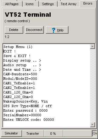
As already mentioned in the previous chapter, press F12 one or two times (with the focus in the client window) to invoke the remote device's system menu.
To terminate a remote control session, click the 'Disconnect' button. Under certain conditions, the remote server may also decide to terminate the interactive remote control session by itself (for example when a file transfer has been initiated by command).
Taking screenshots for the documentation (without a camera)
The featured described in this chapter only exists in a few devices (especially those not equipped with an embedded web server, due to the lack of a suitable interface).Remote Screenshot via CAN or serial port / USB VCP (using MKT's Programming Tool)
Since 2025-12, depending on the target's available interfaces and firmware, this is possible via CAN (in rare cases, via CANopen) or via USB / Virtual COM Port.The 'transport medium' must be selected in the programming tool, as already explained for a remote control connection. Next, in the programming tool's main menu, select
Transfer .. Screen Snapshot via Remote Connection .
This opens a new window, with the status line indicating being 'connected' (or not):
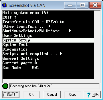
Screenshot of the 'Remote Screenshot' window
Depending on the configured CAN baudrate or USB/RS-232 speed, this may take some time.
Alternatively, the image can be updated periodically by clicking 'Start' while holding the SHIFT key on the PC's keyboard pressed.
When finished (if the device firmware supports Remote Screenshots), click 'Ok'. The screenshot utility will ask for a filename (and destination folder), and export the captured image as a windows bitmap file which can be imported into any decent image processing program (e.g. IrfanView), to convert it into other formats (*.png, *.jpg).
Remote Screenshot via USB / Media Transfer Protocol ("system/screenshot.bmp")
Devices with a real USB device stack (not just a UART <-> USB adapter chip) may support reading the graphic framebuffer as a bitmap file via USB MTP (Media Transfer Protocol).For such devices (e.g. MKT-View V, since 2026), you don't even need the programming tool to make screenshots. Simply copy the file "screenshot.bmp" from the device's "system" (one of the device's internal storage media) into a local folder of your choice, or double-click it to open the file with an image viewer:
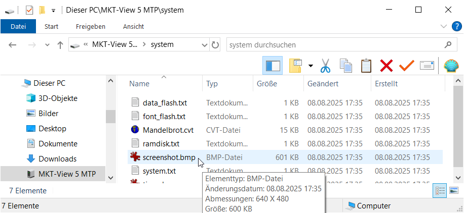
Accessing 'screenshot.bmp' in an MKT-View V via USB / Media Transport Protocol using 'Explorer'.
("Dieser PC" = "This PC", formerly known as "My Computer" on Windows system with english language)
Other files in the MKT-View's "system" folder (which is the storage medium for virtual files, accessable via USB / MTP like files on a smartphone) are listed in a later chapter.
- See also:
-
Overview , XMODEM /
YMODEM file transfer , System
Menu,
Remote displays with VNC / RFB (remote framebuffer control via TCP/IP) .
Storage Media and Files accessable via Media Transfer Protocol
Beginning in 2026 with the MKT-View V (and similar devices with a real USB device stack), files can be transferred via USB, using the Media Transport Protocol (MTP, as used in digital cameras and smartphones to exchange files).As a 'composite' USB device, the MKT-View (e.g. MKT-View V) presents itself to the USB host (e.g. a "Windows PC") as an MTP device with multiple storage media, shown below along with their typical contents:
"Dieser PC" / "This PC" (a dummy entry in 'Windows Explorer', kind of virtual root for 'anything local')
  |
  |-- MKT View V MTP  : Name of the USB device's MTP file server
  |    |
  |    |-- data_flash : An internal storage medium, no 'real files' here but objects in on-board Flash
  |    |    |
  |    |    :
  |    |
  |    |-- font_flash : Another internal storage medium, used for user defined fonts
  |    |    |           for special applications (rarely used today, in favour of scalable vector fonts)
  |    |    :
  |    |
  |    |-- ramdisk : A volatile internal storage medium (SDRAM), accessable via script,
  |    |    |      or a "dropzone" to upload files to the device (RAM) with 'Windows Explorer'.
  |    |    |
  |    |    |      When uploading a *.cvt file into this storage medium on the device
  |    |    |      (e.g. using "ramdisk" as the file's dropzone in Windows Explorer),
  |    |    |      the file will not be stored permanently in the device's onboard Flash.
  |    |    |      This is faster than storing the display application (*.cvt) permanently
  |    |    |      in Flash memory - where it would be stored when dropping a *.cvt file
  |    |    |      into the 'system' storage.
  |    |    |      Thus, executing a display application in the 'ramdisk' can save some time
  |    |    |      during the development phase, and avoid stress to the onboard Flash memory.
  |    |    |      Similar as when 'running an application in RAM' via script command system.exec,
  |    |    |      after rebooting, the MKT-View will not start the application in the 'ramdisk'
  |    |    |      but the application stored in 'system' (a dedicated area in onboard Flash).
  |    |    :
  |    |
  |    |-- system : A virtual storage medium for files generated 'on-the-fly' when read via MTP;
  |    |    |       or another "dropzone" when uploading files to the device with 'Windows Explorer'.
  |    |    |
  |    |    |-- data_flash.txt, font_flash.txt, ramdisk.txt :  When read, returns a short summary
  |    |    |              about the related storage medium (Flash memory usage, free space, etc)
  |    |    |-- application.cvt : When read, the currently loaded application (something.cvt) is converted
  |    |    |             back from 'binary' (from the internal storage) into text, and sent like a file.
  |    |    |             Note: This conversion is not lossless ! Uploading a display
  |    |    |             application as a *.cvt file into the device (where it will be parsed from the
  |    |    |             ASCII strings in that file into 'something binary' for storage in internal Flash),
  |    |    |             and reading it back (which means converting back from 'binary' to 'text')
  |    |    |             will not result in exactly the original file ! At least, if the original
  |    |    |             file got lost, you can retrieve something similar from the device.
  |    |    |             Instead of the placeholder 'application.cvt', the currently loaded *.cvt
  |    |    |             appears in the file listing with its original name, e.g. "BrakeTest.cvt" .
  |    |    |             Note: If the display application was protected / encrypted when loaded
  |    |    |                   into the device, it will still be encrypted when read
  |    |    |                   from the device !
  |    |    |      When uploading a *.cvt file into this storage medium on the device
  |    |    |      (e.g. using "system" as the file's dropzone in Windows Explorer), the file
  |    |    |      will be stored permanently in a reserved area of the device's internal Flash.
  |    |    |      This involves erasing and reprogramming a couple of Flash sectors,
  |    |    |      which takes some time (in contrast to uploading into ramdisk).
  |    |    |
  |    |    |-- screenshot.bmp : When read, this "file" creates a screenshot of the device's graphic
  |    |    |             framebuffer, converted into a Microsoft Windows compatible bitmap file.
  |    |    |             Can be opened with any decent 'image file viewer' - even under Linux ;o)
  |    |    |
  |    |    |-- system.txt : When read, the MKT-View firmware generates a short report about
  |    |    |                 the "system", including (when available / measurable) ...
  |    |    |      * Supply voltage, Ultracap voltage
  |    |    |      * Temperature (internal, measured near the CPU or the TFT display)
  |    |    |      * Raw analog input values (in 'A/D converter units')
  |    |    |      * Amount of memory (RAM, Flash) used by the application, display,
  |    |    |        script, optional CAN logger, etc
  |    |    |
  |    |    |-- can_bus_status.txt : When read, the device firmware generates a report with...
  |    |    |      * the current bitrate configurations of all CAN interfaces
  |    |    |      * CAN bus status flags, number of messages received and sent per bus
  |    |    |      * a snapshot with the most recent CAN messages received from /
  |    |    |        sent to all interfaces (as far as the CAN message FIFOs permit)
  |    |    |    Note: If "can_bus_status.txt" is not displayed in the list of files
  |    |    |          on MTP storage medium "system", this feature had to be sacrificed
  |    |    |          due to the shortage of internal Flash. This applies especially
  |    |    |          to firmware variants with optional features like XCP
  |    |    |          ("Universal Measurement and Calibration Protocol") .
  |    |    |
  |    |    |-- XCP_Master_Config.a2l : If this file is listed on MTP storage medium "system",
  |    |    |        the device firmware was compiled with the optional XCP MASTER functionality.
  |    |    |        At the time of this writing (summer 2026), the XCP MASTER (as well as
  |    |    |        the SLAVE) was in an experimental stage, only available for the MKT-View V.
  |    |    |
  |    |    |-- XCP_Slave_Config.a2l : If this file is listed on MTP storage medium "system",
  |    |    |        the device firmware was compiled with the optional XCP SLAVE functionality.
  |    |    |        At the time of this writing (summer 2026), the XCP SLAVE was in an
  |    |    |        experimental stage, and only available for the MKT-View V.
  |    |    |    If there is sufficient demand by users, details about the integration of
  |    |    |    an XCP Slave or XCP Master (and how to configure them via USB / MTP)
  |    |    |    will published in a separate file, linked from here.
  |    |    :
  |    :    ?
  :    ?
  ?