
CAN Logger / CAN Snooper
![]()
![]() (only available for certain terminals
with 16- or 32-bit CPU and a special firmware variant - see feature matrix)
(only available for certain terminals
with 16- or 32-bit CPU and a special firmware variant - see feature matrix)
More details about the CAN logger is available online, see CAN Logger Utility (external link, requires internet access).
- Scope
- Usage of the CAN Logger
- Usage of the CAN Snooper
- Internals
- interpreter commands/functions to control the Logger / Snooper :
logger.run, logger.stop, logger.trigger, snooper.run, .. - Interpreter commands/functions to control the Flash memory card:
card.insert, card.remove, card.state, card.dspace, .. - Interpreter command to set/clear the 'power-good-flag' (only for MKT-View "PLUS")
- file formats
- storage media
- power supply
- interpreter commands/functions to control the Logger / Snooper :
- Legal Terms
See also (external links) :
- Manual for the programming tool (general)
- Manual
for the Logger Configuration / File Conversion tool
(*)
Includes detailed descriptions of the PC utility for configuring the logger and converting the logfiles into other file formats.
(*) This file may be in another directory, so the link may not work if you changed the default directory during installation. - Printer-friendly PDF with the description of the CAN-Snooper
- Declaring 'loggable' variables in the script language
- Simplistic CAN logger implemented completely as a script
Scope
The CAN-Logger/Snooper is an extra software feature in certain terminals. A special firmware is needed to use the features described in this document, and the terminal (e.g. MKT-View II / III / IV / V) must have a memory card adapter.
At the time of this writing, the CAN-Logger/Snooper was only supported by the following terminal...
- MKT-VIEW "plus" with 40 MHz clock, CF card slot, and a special firmware
(art11089.hex).
Note: In this firmware, the CAN Snooper and CAN Logger functions must be enabled by entering a special unlock code. If you want to use one of these functions but haven't unlocked it yet, please contact the manufacturer. Only if you ordered the terminal with this functions already unlocked, you don't need to go through the unlock procedure. - MKT-VIEW II with 32-bit CPU, 4.3" colour display, and memory card.
- MKT-VIEW III with 32-bit Cortex-M3 CPU, 4.3" colour display, and memory card.
- MKT-VIEW IV with 32-bit Cortex-M4 CPU, 7" colour display, and memory card.
- The CAN-Logger
-
writes the received CAN traffic to a disk file, message-by-message. To reduce
the file size, the CAN identifiers of the logged messages can be selected
(from a CANdb file or "manually").
-
normal "terminal" function remains active in CAN Logger mode
(with reduced performance = lower page update rate if bus load is high) - high-resolution timestamp for received messages
- no display from the CAN logger, it works silently in the background
- logfile must be analyzed on a windows PC later
- limited message rate due to hardware restrictions (as specified in the hardware manual, which is not part of this document)
-
normal "terminal" function remains active in CAN Logger mode
- The CAN-Snooper
-
is a simple CAN analyzer utility to monitor "unknown" CAN traffic. Received
CAN messages are displayed on the terminal's screen.
- normal "terminal" function is disabled in CAN Snooper mode
- sorted by identifier (not as a scrolling list, which would be useless on a slow-reacting LCD).
- scrollable screen (if more CAN IDs are received than would fit on the screen)
- up to 2048(?) different CAN identifiers can be displayed simultaneously
- hexadecimal display of message ID and data bytes, plus counter or timestamp or interval time
- CAN Snooper is activated and controlled via menu on the terminal screen
- no PC required ! ! !
- a few "signal decoders" can be defined for decimal display of a signal's value
- almost unlimited message rate (100% bus load at 500kbit/sec can be tolerated)
- acoustic signals can be triggered upon the reception of certain messages
The next chapters provide some information about the Logger- and Snooper mode. More detailed information is available in the online help system of the CAN Logger Utility but not here (in the documentation of the terminal programming tool).
Usage of the CAN Logger
Note: Details about the configuration of the CAN logger is in the
manual of the CAN Logger Configuration
Tool, which is not the scope of this document !
Introduction
The CAN Logger can be used these two basic modes:
-
Log 'all received messages', no matter how frequently they are transmitted.
Advantage: Message timing and frame rates can be reconstructed later
Disadvantage: Unpredictable logging capacity in terms of recording time. Danger of system overload. -
Log the 'latest received messages' with a limited recording interval.
Advantage: You know how many hours of data can be logged. System overload is unlikely.
Disadvantage: Cannot see the run of the curve in between the recording intervals
The messages which shall be logged can be selected with a special Logger
Tool (which is a separate PC program). The signals which shall be logged
are be selected from a CANdb file, which is loaded into the logger tool.
The logger configuration tool produces a configuration file called "logger.clc"
which must be copied to the CF card. The description of that config tool
is not the scope of this document, please look into the manual or help system
of the logger configuration tool if you need more info !
The logged file(s) are binary files which can be converted with the logger
tool into textfiles, which will then contain the decoded signal values (not
the raw CAN messages). The textfiles can then be loaded into other programs
like Excel(?), DIAdem(??), and possibly a number of other programs which
must be able to import data from text files.
The logger configuration is loaded from a small textfile named LOGGER.CFG, which must be placed in the root directory of the memory card. Usually this file will be created by the Logger Tool; it is your job to copy this file to the memory card.
The maximum capability in terms of "messages per second" etc is defined in the firmware release notes, which are -for good reasons- not part of this document. If you read this document as part of the help system of a terminal programming tool, you will find the firmware release notes in the file ??\firmware\relnotes.htm .
Controlling the CAN logger through the terminal application
Originally, the CAN logger was a separate module which had nothing to do with the display application. But in the meantime, it is possible to control the CAN logger from the terminal program. To do this, some interpreter commands have been implemented (see appendix). For example, you may want to "trigger" (start and stop) the logger using the terminal's built-in analog input (using a 12-bit ADC). You could use a set of event definitions in your terminal application like this (taken from LogDemo1.cvt) :
How does this work ? The interpreter function ain1 returns
the current value from the A/D converter. TrigOld is a user defined variable
which hold the previous analog value. If this value exceeds 500, while
the previous value was below 500, the logger will be triggered. If the new
value reaches 200 or less, while the previous value is above 200, the logger
will be "un-triggered" (which doesn't necessarily mean it stops; due to the
post-trigger option). Event nr 27 sets the "old value" to the "present value"
for the next time the events are evaluated.
Of course, these definitions may be used as global events too, if they shall
be active regardless of the current display page.
Many years after the introduction of the CAN logger in the MKT-View "Plus",
devices equipped with a CAN logger also have a built-in script language.
With additional commands in the script language (listed in the following
subchapters), such devices (like MKT-View III/IV) offer new features like..
- Script-controlled start and stop of logging ("trigger")
- Script-driven playback of logfiles to the CAN-bus
Extended Logger Control via Script
Script-driven playback of recorded logfiles
Logger Config/Control menu in the programmable terminal
There is also a tiny control menu for the CAN logger built inside the terminal. It is mainly used for "field" debugging purposes. In most cases, you (or the operator) won't need it.
- Note:
-
The CAN Logger is usually configured with an extra PC program ("CAN
Logger Configuration Utility") which can be downloaded from the MKT website.
So you will usually not need the CAN Logger menu inside the terminal, but it can be quite helpful for troubleshooting without a PC.
|
→ |
|
→ |
|
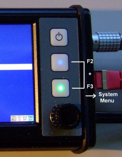
( Entering the CAN Logger config/control menu in an MKT-View III )
To enter the CAN Logger menu...
-
press the System Menu combination (MKT-View: press 2nd and 3rd function key
simultaneously).
The terminal enters the "Main System Menu" -
In the Main System Menu, select "CAN Logger Config" and press the Enter key
(MKT-View: rotary button).
The terminal enters the CAN Logger Menu, similar as the one shown above.
The text cursor and/or the inverse selection bar show the currently selected menu item (or edit field). To navigate through the menu, use the up/down keys, or -if the terminal doesn't have up/down keys- turn the rotary button. To select a function, press the Enter key (or the rotary button).
Logger menu has the following items (some of them explained further below, click on the links):
-
Exit logger without saving
Returns from the logger menu to the caller (either the terminal application or the system menu, depending on how you entered the Logger menu) -
File operations
Load logger configuration from a file, save modified settings in a file (usually LOGGER.CLC) -
Buffer/mode settings
Select which messages shall be logged, and how the logfiles shall be written (FIFO mode, maximum file size, etc) -
Signals & Identifiers
Shows the names, message ID's, but also the current values of the logged signals. Very handy to check if the logger works properly, if you don't have a PC near you ! -
Messages & Identifiers
Shows a list of logged CAN messages. Note that a message usually consists of several messages ! -
Trigger settings
Change trigger settings, look at the current trigger status ("is it triggered or not ?"), etc -
Other logger settings
Displays some additional parameters of the current logger configuration, including a user-defined "info"-string, and a name of the databases which were used when preparing the logger configuration with the PC program ("Logger Configuration Utility"). Except for the "info"-string, these cannot be edited here. -
Logger diagnostics
Shows the current logger state, the number of received CAN messages, the number of messages which have been written to the memory card, the remaining disk space, etc .
CAN Logger Menu "Signals and Identifiers"
This submenu shows a list of all logged CAN (or LIN) signals, along with their names, CAN identifiers, and the actual raw values or scaled ("physical") values. The display mode (ID, raw values, or physical values) can be selected in the second menu item ("Display mode").
List of CAN signals (#1/256) Back to main menu Display mode: Physical values ByteCounter 0.00 CounterStatus 0.00 LongCounter 0.00 Thermo1 20.01 Thermo2 20.02 Thermo3 20.03 Thermo4 20.04 |
CAN Logger Menu "Messages and Identifiers"
This menu shows a list of all logged CAN (or LIN) messages, with their names and CAN/LIN identifiers.
List of CAN messages (#1/128) Back to main menu 0x00000123 Counters 0x400000DE Thermo2_ID_DE 0x400000E1 Gearbox_Msg1 0x400000E2 Gearbox_Msg2 |
Functions specifically for the MKT-View II / III / IV
ToDo: explain....
- why the power-flag is much easier to use (and "read-only") in the MKT-View II / III / IV (due to the internal UPS)
- how to display the activity of the memory card, and the CAN logger, in the system icons
- how to record voice messages, using the same filename as the current logfile except for the file extension "wav"
Usage of the CAN Snooper
The CAN snooper is a simple CAN analyzer on the CAN message level. The intended
use is to monitor traffic in an "unknown" CAN network, with the possibility
to decode or highlight certain signals in certain messages
on the terminal screen without any premises like the availability of a CAN
database file.
The 'CAN Snooper' can also be used as a LIN-bus monitor, if one of the device's
serial ports is assigned 'as a LIN-bus' to the logical interface CAN3 or (preferrably) CAN4.
Details about setting up CAN3 or CAN4 as a LIN-bus are here.
To launch the CAN Snooper, use the
system menu or the
interpreter command snooper.run in one of the
user-defined display pages .
( Entering the CAN Snooper config/control menu in an MKT-View III )
Notes:
Manually open the CAN snooper as explained further above.
In the 'CAN Snooper Menu', enter 'Other functions ...".
Set parameter 'Boot in Snooper Mode' to 1 (one,ON),
and in the same menu, invoke 'Save Snooper-Config'.
To restore the device's 'normal' function as a programmable display system,
set 'Boot in Snooper Mode' back to 0 (zero,OFF), save again, and exit.
Per default, the received messages are displayed in hexadecimal form, sorted by identifier.
In older devices (MKT-View II/III/IV), the leftmost column showed the CAN identifiers, usually in hexadecimal format.
The most significant bit(s) indicated the bus number and the 11/29-bit-flag:
- 0x00000000 (bits 31..29 clear) indicates its a normal 11-bit-ID received from the first CAN interface (bus 1)
- 0x20000000 (bit 29 set) indicates its a 29-bit-identifier, also called "extended message frame"
- 0x40000000 (bit 30 set) indicates the message has been received with the 2nd CAN interface (bus 2)
- 0x80000000 (bit 31 set) indicates the message has been received with the 3rd CAN interface (bus 3 for future versions)
-
0xC0000000 (both bit 31 and 30 set) indicates the message has been received on the 4th port ("CAN4"),
which may in fact have been configured as a LIN bus interface !
After the message ID, up to 8 data bytes from the last received CAN-message or LIN-frame are shown in hexadecimal form (decimal won't fit on the small screen!).
At the right side of the screen, some additional info can be displayed. By default, only the frame counters for all individual IDs are displayed. A one-letter-token indicate which "additional info" is displayed at the moment. Possible tokens are:
- c= Counter. Every received CAN ID has its own counter, so there may be up to 2048(?) different counters.
- p= Period. This is the time interval between the last two received messages, displayed in milliseconds.
- f= Frequency or Frame rate. This is the count of messages per second.
- t= Timestamp. Because the screen is too narrow, you may have to scroll horizontally to see the complete timestamp.
You can select which of these 'additional infos' shall be displayed via the CAN Snooper's menu (explained later). Also, besides the raw hex data, the physical values of the signals can be displayed along with the message (Display options.. View: "Both, combined" instead of "Raw CAN frames").
The selection bar can be moved through the message list with the cursor up/down
keys, or -if the terminal has no cursor keys- with the rotary button. The
selection bar will remain on the same CAN ID even if "new" messages are merged
into the sorted list.
The upper line shows the function key assignments. The function keys can be used to scroll the message list rapidly ("page up", "page down"), to mark or hide certain messages, and to scroll the display horizontally (if the display has an insufficient number of characters per line). The set of function key assignments can be changed with a function key itself (usually F3), or through the menu. Some abbreviations for the key functions are:
- PgUp: Scroll the list one page up
- PgDw: Scroll the list one page down
- Mode: Switch to the next 'mode', or set or key functions
- Menu: Enter the CAN Snooper's main menu
- Dump: Dumps the complete message buffer into a text file (not just the screen)
- Mark: Mark the currently selected message (because it's something special)
- Hide: Hide the currently selected message (because I don't want to see it any longer)
The Snooper is entirely controlled from a menu on the terminal screen. Use
the function keys and the rotary button to navigate through the menu and
to modify parameters if necessary. The CAN Snooper's menu structure is explained
in the next chapter.
Snooper Main Menu
To open the CAN Snooper's main menu, press the ENTER key (or press the rotary button down, which is the same throughout this document). A popup menu similar as shown below will open:
CANsnoop F1:Pg↑ F2:Pg↓ F3:Escape E:Select 00000333 5E 73 F3 CA DE 4B c=1234 00000334┌────────────────────────┐=1234 00000335│CAN Snooper Menu (1) │=1233 000003FD│Close menu & continue │=1234 000003FE│Clear message list │=1234 40000333│RX-Action id=00000333 > │=1234 40000334│CAN BUS parameters > │=1234 40000335│Display options > │=1233 400003FD│Record / Replay msgs > │=1234 400003FE│Other functions > │=1234 │Quit snooper │ └────────────────────────┘ RxCnt=19752 I=1/10 |
To navigate through the menu, use the cursor up/down keys. If your terminal has no cursor keys, turn the rotary button.
To open one of the submenus, or modify a numeric parameter in a menu, press the enter key (or the rotary button).
The functions in the main menu are:
-
Close menu [and continue]
Closes the snooper's popup menu to have a full-screen view of the received messages again -
Clear message list
Erases the internal list of received messages, including all message counters etc. -
Define an RX-action
Tell the snooper "what to do when a message with a certain ID has been received". This may be an acoustic signal, etc.
-
CAN bus parameters
Lets you modify the CAN baudrate and -possibly- other CAN parameters in future.
CAUTION ! The standard terminal is always an ACTIVE CAN NODE. If you select the wrong baudrate, the CAN controller sends thousands of error frames which may cause a catastrophy if you try this in a vehicle at 200km/h ! There may be a special hardware with a disabled CAN output driver (aka 'passive monitor') which avoids this problem.
- Display options
Select what shall be displayed besides the hexadecimal message data, and show/hide certain unwanted messages. In devices with a sufficiently large screen, you can also switch the 'View'-option between 'raw CAN message display' (hex), decoded 'signal values', and a 'combined' display (which shows both, the raw CAN frame and the signal values decoded from that frame, along with their names and physical units).
Devices with CAN FD have some additional entries in the 'Display options' menu, e.g. Multi Line mode to break long data fields into multiple lines of text. - Signal decoders
Explained in another chapter -
Record / Replay messages
The CAN-snooper can also be used to record selected messages (or, if the bus load permits, all received messages) as a Vector 'ASC' compatible CAN logfile. The contents from such a file can also be played back. Details in
Note: Logfiles recorded this way (as *.asc) can also be 'played back' into the simulator. -
Other functions
Less frequently used functions like the file counter for CAN message dumps. -
Quit snooper
Exit snooper mode and resume normal operation as "programmable terminal". If the snooper has been invoked through the system menu, "Quit" takes you back to that menu. If the snooper has been invoked from a user-programmed display page, you will return to that page.
Caution: Using the snooper disables the "normal" CAN message processing of the application !
Signal Decoders in the CAN Snooper
From the received CAN- and/or LIN- traffic, a few signals can be isolated for display purposes.
You define a few signal parameters, and the CAN snooper will turn bits and bytes from a CAN message into human-readable decimal numbers.
In some devices (since 2017/08), the 'signal decoders' will be preset with the
signal definitions imported from a CAN database (*.dbc) into the display application
(*.cvt). Since the display itself cannot access the original database, it makes sense
to keep all CAN signal definitions in the *.cvt file even if you don't need them
as display variables (in your normal display applications).
Alternatively (if the imported 'CANdb' table had been stripped from the display application by the developer),
the CAN snooper may be able to extract a few CAN signal definitions from the display variables:
In the CAN snooper menu, select Other functions, Copy Defs from Display.
This way, you can easily check the decoded signals as shown in the screenshot further below.
- Short form:
- If you keep the signal definitions in the *.cvt, you don't need to enter the
signal decoders manually (as explained in the rest of this chapter) because the
CAN Snooper will already know how to decode the incoming traffic into physical values.
In that case, skip the rest of this chapter (you don't need it), and watch the decoded values on the screen !
CANsnoop F1:Pg↑ F2:Pg↓ F3:Mode E:Menu GpsMsg1 21 C5 50 42 E2 6B 09 41 c=4038 |_ GpsLat: 52.192509 ° |_ GpsLon: 8.5888386 ° GpsMsg2 C0 03 10 47 00 44 00 00 c=11401 |_ GpsTime: 36867.75 seconds |_ GpsDate: 17408 Unix days GpsMsg3 A8 55 C3 3E 9A 99 9F 42 c=11363 |_ GpsSpeed: 0.38151288 km/h |_ GpsHei~t: 79.800003 mASL GpsMsg4 A3 01 F0 00 A4 69 D6 41 c=11401 |_ GpsUni~s: 1504088067.7501 Unix sec GpsMsg5 41 D6 69 A4 00 F0 01 A4 c=11401 |_ MotUni~s: 1504088067.7501 Unix sec RxCnt=83807 I=1/8 |
If signal decoders have been defined (or imported from a *.dbc into the *.cvt file), the current signal values can optionally be displayed along with the CAN-message in the CAN snooper's full-screen display (in the snooper menu: "Display options".."View": "Both, combined"). To show the symbolic message name instead of a numeric message-ID, set "Display options".."ID Format" to "Symbolic".
Names (e.g. CAN-message and -signal names) may have to be truncated for the display. A tilde (~) represents omitted characters in such names. For example, 'GpsUni~s' shown in the screenshot above was originally a CAN-signal named 'GpsUnixSeconds'.
The number of digits for the display depend on the signal's data type. Scaled single-precision 'floats' are displayed with up to 7 decimal digits, 'double'-precision values (64-bit) may be displayed with up to 16 digits.
To configure a Signal Decoder for a particular message, select the message which shall be decoded (so we know the ID) and open the CAN Snooper's main menu. Select "Signal decoders". A popup menu similar to the one shown below will appear:
CANsnoop  F1:Pg↑ F2:Pg↓ F3:Escape E:Select
00000333 5E 73 F3 CA DE 4B       c=1234
00000334┌────────────────────────┐=1234
00000335│CAN Signal Decoders (2) │=1233
000003FD│Back to main menu       │=1234
000003FE│Add decoder id=00000333 │=1234
40000333│Signal01 +0012345678  > │=1234
40000334│Signal02 +0000000000  > │=1234
40000335│Signal03 -0099999999  > │=1233
400003FD│Signal04 -0099999999  > │=1234
400003FE│Signal05 -0099999999  > │=1234
        │Signal06 -0099999999  > │
        └────────────────────────┘

RxCnt=19752 I=1/10
|
Select the menu item "Add decoder id=XXXXX" to define a new signal decoder.
We already know the CAN-ID of the message, because that message has been
selected in the message list. Otherwise,
you would have to enter a 29-bit value without a numeric keyboard now which
may be tricky without a real keyboard.
To define or modify one of the CAN Signal Decoders, another menu will appear on the terminal's screen:
CANsnoop  F1:Pg↑ F2:Pg↓ F3:Escape E:Select
00000333 5E 73 F3 CA DE 4B       c=1235
00000334┌────────────────────────┐=1234
00000335│Edit CAN signal #1      │=1233
000003FD│OK (apply & return)     │=1234
000003FE│Bus&CAN-ID = 0x00000333 │=1234
40000333│L.S.Bit at pos = 00     │=1234
40000334│Nr of data bits= 00     │=1234
40000335│SignalType: Signed      │=1233
400003FD│Byte Order: ?unknown?   │=1234
400003FE│SigName:                │=1234
        │                        │
        └────────────────────────┘

RxCnt=19753 I=1/10
|
As shown in the screenshot, the CAN Snooper needs some more information to decode a CAN signal. These are
- message ID
- position of the least significant bit within the message. Valid bit positions are 0..63 (!!) because a CAN message has up to 8 data bytes.
- count of databits for the signal. Often 8, 16, or 32 bits.
- the signal's byte order ("Intel" / "Motorola" format as in a CANdb signal)
- the signal type ( "Unsigned", "Signed", "Float", or "Double" )
For example, we are interested in a signal with 16 databits which is in the first 'WORD' in the CAN message. We guess the machine which sends the frame uses a CPU with low-byte-first so we set the signal's byte order to Intel (aka Little Endian format). The finished definition would look like this:
CANsnoop  F1:Pg↑ F2:Pg↓ F3:Escape E:Select
00000333 73 55 44 4C 34 59 48 46 c=1236
00000334┌────────────────────────┐=1234
00000335│Edit CAN signal #1      │=1233
000003FD│OK (apply & return)     │=1234
000003FE│Bus&CAN-ID = 0x00000333 │=1234
40000333│L.S.Bit at pos = 00     │=1234
40000334│Nr of data bits= 16     │=1234
40000335│SignalType: Signed      │=1233
400003FD│Byte Order: Intel       │=1234
400003FE│SigName:                │=1234
        │                        │
        └────────────────────────┘

RxCnt=19754 I=1/10
|
In most cases, 16-bit-values will be on even byte boundaries within the CAN data field. Values in Intel format (little endian) are sent low-byte-first, Motorola format (big endian) is high-byte-first. Forget about "Motorola forwards" and "Motorola backwards" - we don't know the difference. Here, the bits inside a CAN-/LIN-frame are ALWAYS numbered as follows, regardless if the sender uses "Intel", "Motorola" or whatever-byte-order:
Byte- |
bit 7 |
bit 6 |
bit 5 |
bit 4 |
bit 3 |
bit 2 |
bit 1 |
bit 0 |
[0] | 7 | 6 | 5 |
4 | 3 | 2 | 1 |
0 |
[1] | 15 | 14 | 13 |
12 | 11 | 10 | 9 |
8 |
[2] |
23 | 22 | 21 | 20 |
19 | 18 | 17 | 16 |
[3] |
31 | 30 | 29 | 28 |
27 | 26 | 25 | 24 |
[4] |
39 | 38 | 37 | 36 |
35 | 34 | 33 | 32 |
[5] |
47 | 46 | 45 | 44 |
43 | 42 | 41 | 40 |
[6] |
55 | 54 | 53 | 52 |
51 | 50 | 49 | 48 |
[7] |
63 | 62 | 61 | 60 |
59 | 58 | 57 | 56 |
Like in many programming languages, bits and array indices are numbered from zero to "N minus one". The very first bit in the data field is BIT ZERO, not "BIT ONE".
After specifying all signal parameters, apply the changes and return to the previous menu by selecting "OK". This takes you back to the signal decoder menu, where the decoded values will be displayed as soon as new CAN messages with a matching identifier have been received. Decoders which have not received a signal yet will show the value '-99999999' which means 'invalid'.
Recording and playing back messages with the CAN snooper
In devices with a memory card interface, the CAN snooper (!) can also be used to record messages,
and play back such recorded messages to the bus (for testing purposes). The file format is compatible
with an ancient version of Vector's CAN 'ASC' (ASCII, i.e. text) format.
|
→ |
|
'Internal' playback means messages read from the selected file are only played back 'internally' (into the firmware's CAN-message-handler).
'Replay to CAN-BUS' means the messages read from the file are actively transmitted by the MKT-view to the CAN bus(es).
Note: ASC files recorded this way can also be played back in the simulator (programming tool) as explained here.
The ASC file format requires a lot of bytes for each message (due to the fact that it's a text file), thus the CAN-snooper is not a replacement for the CAN logger. The same applies to logging CAN message 'as text' in the script language.
Message Dump in CAN Snooper mode
For a convienient examination of the received traffic on a CAN (or LIN) MESSAGE level,
the contents of the message buffer can also be 'dumped' into a textfile on the
memory card. You can examine, edit, and print the dump file on a PC
later, all you need is a simple text editor.
Unlike the 'Record' option explained in the previous chapter, the 'Message Dump'
doesn't record continuously, but takes a snapshot of the message identifiers,
and their counters (i.e. 'statistics').
The dump file format is the same as on the message screen, which means the dump file will show the last received CAN messages sorted by identifier.
-
Sample dump file (from an older device with only two CAN interfaces): -
; CANsnoop dump nr. 7

    ; started 2003-08-28 13:36:59

    ; dumped  2003-08-28 14:00:28

    00000003 08 BD 28 5E 4B 94 11 AF c=233

    000003FF 08 BC D3 5E 7E E9 7F 2F c=231

     ...
-
Sample from a device with more than two CAN interfaces (e.g. MKT-View V with four CAN / CAN FD ports):
Here, the "bus-number" isn't encoded in the two most significant bits of the message ID, but will be displayed in an extra column (actually, the first column). -
; CANsnoop dump nr. 8

    ; started 2025-01-27 15:20:00

    ; dumped  2025-01-27 15:21:53

    1 00000003 08 BD 28 5E 4B 94 11 AF c=233

    1 000003FF 08 BC D3 5E 7E E9 7F 2F c=231

     ...
The header of a dump file includes date and time information, taken from the terminal's battery-buffered clock.We use the one and only 'logical' date- and time format, which is YYYY-MM-DD hh:mm:ss, the International Standard Date and Time Notation proposed by ISO 8601. Do a web search on "ISO 8601" for more info. For the future, avoid formats like YY/DD/MM, DD/MM/YY etc in text data files which may have to be processed on machines in other countries.
The filenames are produced automatically in the format "candmpNN.txt", where NN is a decimal number (index) from zero to 99. Whenever a message dump has been written to the CF Memory Card, the index is incremented. You can modify the current dump index in the Other Functions menu.
To generate a CAN message dump, you can..
- press the function key assigned to the 'Dump' function (if necessary, press 'Mode'=F3 a couple of times until 'F2:Dump' is available in the title line),
or
- select the function Dump buffer to file in the Other Functions menu.
Note: The message dump function may take a few seconds to produce the text file. During this time, some messages will not be counted if there is a high bus load. You will notice an increasing Lost Message Counter in that case !
Display format for 'CAN FD' in Snooper mode
Devices equipped with a CAN FD capable controller (e.g. MKT-View V) can also display received CAN FD frames in Snooper mode.If the payload (up to 64 bytes per frame) exceeds the width of a display line, the hexadecimal payload display will be truncated on the screen. Optionally (in 'Multi-Line' mode), the payload can be broken up into multiple lines on the screen.
To easily tell 'FD' frames (with or without bitrate switch) from normal CAN traffic, FD messages have at least one of the CAN-FD-specific flags (*) displayed in human readable form, and their data field is prefixed by the number of data bytes in squared brackets. Example (MKT-View V with an extra column for the bus number:
|
- (*) The CAN Snooper tries to use the shortest possible form for the 'message dump'.
- As long as the snooper didn't receive any 'FD' frame (but only 'classic CAN'),
it will not show size indicators (number of bytes displayed in squared brackets),
and it will not mark 'classic CAN' frames as 'CAN'.
Three-letter tokens that may appear in the message dump (between the message identifier and the data field) are:
FDF : Marks an FD frame without a bitrate switch (and without an 'Error State Indicator')
BRS : Marks an FD frame with a bitrate switch (different bitrate for the data field)
ESI : 'Error State Indicator' : Indicates 'severe trouble' in the CAN FD network !
CAN : Marks a 'classic' CAN frame (only displayed if CAN FD frames are also present)
RTR : 'classic' Remote-Transmit-Request (only exists for CAN, not for CAN FD)
RRS : CAN FD "Remote Request Substitution"
With their maximum payload of 64 bytes, CAN FD frames often don't fit in a single display line. As far as the display width permits, the line with the bus number, message ID, frame type, and length ("DLC") only shows the first eight data bytes in hexadecimal form.
To see all data bytes, press ENTER to open the snooper menu, and select Display options .. Multi Line:
|
- "when selected" :
- Show the entire data field only for the currently selected frame in the list (via encoder or up/down keys).
- "automatic" :
- Show the entire data field in multiple lines of text if the payload doesn't fit in a single line,
regardless of the currently selected frame.
- "Off (never)" :
- Regardless of the payload length, only show one line per message ID, and truncate the payload.
|
Internals
Interpreter commands to control logger and snooper
Some of the logger / snooper functions can be controlled or activated from the user-programmable terminal application. For example, you can activate the CAN snooper from your own menu, or through a hotkey (etc etc). The interpreter functions are:
-
logger.run -
Activates the CAN logger, but does not
necessarily trigger it (depending on the configuration, see
logger.trigger). Caution: If the supply power is 'unsafe' for any reason, the command logger.run will have no effect. Depending on the hardware, the power-good-flag must be set to one (power=1) before logger.run has an effect.
-
logger.stop -
Stops the CAN logger. The logfile on the memory card is closed, so you can
safely remove the card. No popup window appears (in contrast to the
'card.remove' command). The logger will also
stop automatically when the power-good-flag is cleared
(power=0).
-
logger.trigger(X) -
Triggers a recording (X=1) or clears the trigger flag (X=0). Does not close
the logfile. Intention: Manual trigger or trigger by the user-programmable
terminal application. Examples:
logger.trigger(1): rem Start recording to the CF card
logger.trigger=1: rem Same effect as above, only different syntax
logger.trigger=0: rem Stop recording, but keep buffering received frames
Note about "logger.run" vs "logger.trigger":
Setting the trigger (=begin writing to the logfile) with this command automatically includes activating the logger (logger.run). But, if the logger was not running when executing the trigger-command, there will be nothing in the pretrigger-buffer.
So, if you need pretrigger-data, activate the logger before triggering it ! More info on that can be found in the documentation of the CAN Logger Configuration Utility.
-
logger.info -
returns the "info string" which has been defined with the logger configuration
utility. The info string cannot be modified with this routine !
-
logger.file -
returns the name of the current logfile (as a string). The filename cannot
be modified with this routine !
-
logger.fnr -
returns the logfile sequence number (as integer value). The value can only
be read, but not modified with this routine !
-
logger.fspace -
returns the remaining space in the current logfile in KByte. The result is
only valid if a logfile is opened at the moment. The limit may be the remaining
disk space, but also the user-defined maximum file
size.
-
logger.load -
The relative CPU load caused by the logger. Unit is percent * 100 (two places
after the decimal point). A value greater than 100.00 means "severe overload"
(Reasons: message rate too high, decoding of trigger conditions too complicated,
access to the memory card too slow, etc). Only for testing purposes.
-
logger.menu(X) -
Enters one of the logger's built-in configuration or diagnostic screens,
which are otherwise only accessible via the terminal's system menu.
The numeric parameter X defines, which of the screens shall be entered :
logger.menu(0)= Enter the logger's main menu
logger.menu(1)= Show the basic logger states (CAN logger diagnostics)
logger.menu(2)= Show the current trigger conditions
logger.menu(9)= Open the file selector to load a new logger configuration(*)
Note: There may be other values which are not listed in this document !
(*) It is highly recommended NOT to load a different logger configuration during runtime, because the new CAN message filters cannot be applied without rebooting the terminal.
-
logger.rcnt -
returns the count of CAN messages received (but not necessarily "written")
by the CAN logger.
-
logger.wcnt -
returns the count of CAN messages written to the logfile (since starting
the logger).
-
logger.lost -
returns the count of "lost" CAN messages in the CAN logger. Lost messages
are caused by severe overload, see
"logger.load" for details.
-
logger.state -
returns the current state of the CAN logger as a numeric value. Possible
results :
0 = "stopped" (file not open, or buffer not filled in interrupt)
1 = "engaged" (file open, ISR active, but not triggered yet)
2 = "triggered" (file open, ISR active, AND "triggered" )
3 = "post-triggered" (after triggered). Only occurrs if the post-trigger time in the logger configuration is non-zero.
-
snooper.run -
Enters the CAN snooper mode from your
application.With this command, there is no need for the user to navigate
through the terminal's system menu !
Planned: Examples for the usage of these commands are in the files
"LoggerTest.cvt" or "LogDemoX.cvt".
Interpreter commands and -functions to control the memory card
You may want to change the memory card while leaving the power supply of
the terminal on. This is critical as explained in the chapter
"power supply". In fact, it is absolutely illegal
to remove the card while any writeable file is open ! If you want to
offer the user the possibility to INSERT or REMOVE the memory card while
the power is on, use these interpreter commands (maybe in a reaction method
for a menu, or a programmable function key) :
-
card.insert -
Opens a small popup window which asks the user to insert a memory card. The
popup window disappears automatically after the user inserted a card. The
logger configuration will be read from the new card automatically. If there
is already a memory card inserted in the CF memory slot, this command does
nothing. This command does not "wait" until the operation is completed !
The display application continues to operate in the background.
Note: The card can only be written if the power supply is 'good' (reliable). See description of the 'power good' flag.
-
card.remove -
Opens a small popup window which asks the user to remove the memory card.
The popup window disappears automatically after the user removed the card.
Before this, all open files will be closed (which is very important, otherwise
the directory structure of the card will be destroyed). If there is no card
in the CF memory slot, this command does nothing.
Note: This command does not "wait" ! The display application continues to operate in the background. For this reason, the command sequence
card.remove : card.insert
makes no sense, because both commands are executed (almost) at the same time. If you want the user to remove one card and insert another, use two different display pages for this task.
-
card.state -
Returns the current state of the memory card as a numeric value. Possible
return values are:
0 = no card inserted
1 = card inserted, properly initialized and checked "ok"
2 = card inserted, initialisation not finished yet
3 = card inserted, but wrong type (unsupported file system ?)
4 = supply of the Compact Flash card is switched off (don't know if card is inserted)
-
card.dspace - Returns the memory card's free disk space in kByte. Caution: This function may take a few seconds to run, if the FAT (file allocation table) has not been read since initialisation. Furthermore, the result may be invalid if the card's file system is not supported (the result will usually be zero then).
Normally you don't need the 'insert' and 'remove'-command. The recommended
operation is to insert a memory card with the logger configuration before
turning the power on, and to remove the card (if necessary) after properly
shutting down the terminal. They are only required if you want to switch
to another logging setup "on the fly".
Interpreter commands to access the 'power-good-flag'
- Note:
- The following chapter about the 'power-good-flag' only applies to the old
'MKT-View Plus', which did not have an internal UPS (uninterruptable power supply).
For newer devices with internal UPS (like MKT-View II/III/IV), the power-flag doesn't have to be set by the display application to kick the CAN-logger alive !
To avoid damaging the Flash memory card, writing to the card may only start if the power supply lines are 'safe' or 'reliable'. An 'unsafe' power supply may be a car's battery voltage before the engine was started. When starting the engine, the battery voltage may drop to 6 Volts, which is not enough for the terminal so it will shut down immediately (at least, for the first series of MKT-View terminals which were in production in January 2004).
To relax this hardware problem via software, the CF memory card is disabled
for any WRITE-access until your terminal application sets the "power good"
flag. This can be done with the following interpreter command:
-
power=1 -
This command means "The power supply is safe now, there is no risk of losing
both supply voltages at the same time".
You may use it in an event definition, triggered -for example- by a comparison of the engine revolution speed. If the motor runs at 1000 RPM or more, set power=1 . If you cannot access the motor's RPM value via CAN, use a hotkey to set "power=1" - with the disadvantage that it will be the operator's responsibility to press the button only AFTER starting the engine.
-
power=0 -
This command means "The power supply is unsafe now, there is the risk that
both supply voltages will fail at the same time".
You may use it in an event definition, triggered -for example- if the motor runs at 500 RPM or less.
Setting "power=0" disables write accesses to the CF memory card. This will cause the terminal to close all files which were opened for writing, including the logfile, etc.
For testing or 'diagnostic' purposes, you can read the state of the "power good" flag like an ordinary variable. But remember, it is YOUR task to keep this flag up-to-date. When reading, the power-flag can have the following values:
- 0: The power is unsafe, because the program has not set it yet (or has set it back to zero for any reason).
- 1: The power is safe. This is the only condition where it is possible to "trigger" the CAN-logger. In all other conditions (power=0 or negative) the logger will refuse to be triggered !
- -1: The power is unsafe, because the voltage at the "standby"-supply input is below 9 volts. This may change if the voltage recovers.
- -2: The power is unsafe, because the voltage at the "standby"-input dropped below 9 volts WHILE the user-defined "power-good-flag" said it was safe. The operator then clicked "Ignore" to ignore a warning message. This condition is dangerous, and can only be resolved by turning the terminal off and on again (there can be no software-solution for this).
The default state of 'power' was zero (for the old MKT-View "PLUS"),
which means power is unsafe, and writing to the memory card is impossible by default.
In later redesigns of the terminal hardware (MKT-View II/III), this was changed:
For all devices with an internal UPS (uninterruptable power supply), the power-flag
is set automatically (by the FIRMWARE, not the DISPLAY APPLICATION) as soon as the
internal storage capacitors ('Ultracaps') are sufficiently charged.
In the sample terminal application "LogDemo1.cvt", you will find an example
for the usage of the power-good flag. In the simple example, the user is
asked to "press any key" as soon as he thinks the power is safe, and to press
the F1 key later before turning the engine off. As explained above, you may
replace this with a more sophisticated solution, using the engine's revolution
speed to set power=0 or power=1.
File formats
Format of 'primary' CAN log files on the memory card
A CAN log file contains everything which you need to decode all all logged signals. For this reason, the header contains a small database with signal definitions in a "textual" form. The CAN logger actually writes messages (not signals) to the memory card. A single data record in the logfile consists of 16 bytes of information, including..
- bus number,
- 29-bit CAN-ID,
- "standard"/"extended" flag,
- timestamp (relative to the last absolute timestamp !)
- count of data bytes actually received,
- and the 8 message data bytes itself.
A complete and up-to-date description of the CAN logger's primary file format
can be requested via email MKT
Systemtechnik. Please ask for the "CAN-logger file format
specification" in your message so everyone knows what we are talking
about ;-) . The logfile format may be described in the
CAN-Logger Configuration Utility,
too.
Format of CAN log files exported "as text"
These files are not produced by the logger itself, but with a special utility program which reads the 'primary' logfiles and converts them to anything else.
Details about the available file formats are in the documentation of MKT's CAN Logger Utility. You can expect at least one "human readable" message format like this:
07046765: 000.s 01 14

07046875: 214.s FF FF FF FF FF FF FF FF

07047040: 214.s 00 00 00 00 00 00 00 00
Beware: all these were future plans by the time of this writing ! The formats are subject to change without further notice .... ;-)
The first column is the timestamp (here in milliseconds), the second is the
CAN identifier with suffix ".s" or ".x" indicating "standard" or "eXtended"
message frame, followed by the message data bytes. The hexadecimal data display
may be followed by an optional comment which contains message and/or signal
name, followed by the decoded signal values in this message.
Format of message dumps from the CAN snooper
Explained in the chapter about the CAN snooper mode. Basically the same format
as the CAN snoopers on-screen message list, sorted
by identifier.
Storage Media
The configuration and data files are stored on a Compact Flash™ memory card for the terminal's CF memory slot (MKT-View I), or memory card (MKT-View II).
Storage medium for the old 'MKT-View Plus' (with CompactFlash memory card)
The configuration and data files are stored on a Compact Flash™ memory
card for the terminal's memory card slot. We tested a few of those cards
from various manufacturers, with sizes between 4 and 512 MByte. Be careful,
because:
For the old MKT-View "Plus", the CF memory card must be DOS-formatted !
Other formats like FAT32, NTFS, etc will not work ! Fortunately, cards with size <= 2GByte
are still DOS-formatted with a 12- or 16-bit FAT by their manufacturer.
Storage medium for MKT-View II / III / IV (with memory card)
These newer devices with 32-bit CPU (ARM) use a memory card, which must be treated
even more carefully than the old (large) CF memory card.
MKT-View II, III, and possibly all later devices support FAT16 and FAT32,
thus they are suited for disk volumes larger than 2 GByte.
- Note
- MKT-View II / III still do not support NTFS, and long filenames,
to avoid hassle with several software patents.
The memory card interface is compatible with MMC, and possibly with similar patent-encumbered products.
General notes about storage media ("memory cards")
The memory cards must be handled with care. Though some precautions were made when constructing the terminal hardware, you should disconnect the terminal from before inserting or removing the memory card to avoid electrostatic discharges. During logging, some files may be opened on the memory card. If there is a sudden loss of power during file writes, the data on the card will be corrupted, and -worst case- the file allocation table and directory structures will be damaged. In the latter case, use your PC and a 'Scandisk' utility to repair the file system.
To avoid corrupted data caused by sudden power failure, the terminal (when
equipped with CF memory slot) requires two separate power lines: A switched
supply voltage, and a permanent supply. More about the terminal's power supply
can be found in another chapter.
Power Supply Requirements (storage media related)
As mentioned in the chapter 'Storage Media',
the terminal must power itself down in a controlled fashion to avoid data
loss on the memory card.
The following section only applies to the older MKT-View I. The MKT-View
II/III/IV have internal uninterruptable power supplies which avoids a lot of
hassle described in this chapter.
In the MKT-View I ("MKT-View Plus"), there is
- a switched power supply line which is used to turn the terminal on and to initiate shut down
- a permanent power supply line from which the power for the shutdown process is taken.
Both supply lines have the same electrical characteristics (specified in the hardware manual). Typical supply voltages are 9.0 to 24 V. If the 'permanent' suppy voltage is missing or below 9 V, the terminal will show a warning message like
Bad standby supply voltage ! |
In this case, you should check the electric wiring, connectors, and -possibly- the battery voltage.
DO NOT CONNECT BOTH SUPPLY VOLTAGES IN PARALLEL ! Data losses and a corrupted file system on the memory card will be the result, when the 'permanent' voltage is turned off together with 'switched' voltage, so the terminal has no chance to close all opened files properly (especially those opened for writing).
Because there may be the risk that both supply voltages may drop below 9 Volts when starting the vehicle's engine, the terminal must be informed if the power is "reliable" or not. More details are in the chapter about the power-command of the interpreter.
If there is something wrong with your supply voltages or the cable connections, you will get this message when turning the terminal's power on :
SOS - Device has not been shut down
[press any key to continue] |
In this case, you should
- Turn the terminal off, this time with a properly connected standby supply voltage. (If you press a key to continue without turning off, the logger will not work because write-access to the memory card is inhibited)
- AFTER turning the power off, remove the memory card from the CF memory slot, and let Microsoft "Scandisk" (or a similar program) try to rescue the data on your memory card. The terminal itself has no such utility - and never will !
- Examine reason for the improper shutdown. Most likely, you have connected permanent and switched voltage in parallel, which is illegal. Use a voltmeter (or -even better- an oscilloscope) to measure the permanent voltage in the moment you turn the "switched" supply voltage off. In most cases the terminal will be turned on and off with vehicle's ignition switch (DL: Zündschloss). Make sure the permanent supply is not turned off with the ignition switch. In a passenger car, the cigarette lighter is sometimes "switched", sometimes not ! More information about the terminal's power requirements can be found in the hardware description.
- Make sure the interpreter command power=1 is not executed too early in your application !
- Turn the terminal on again. If the last shutdown was ok, the "SOS"-message shown above will not appear again.
Notes:
- Power from the "permanent" (or "standby") supply is only drawn for a couple of seconds..
- In fact, the "permanent" supply voltage only needs to last for a few seconds to shut the terminal down properly. The time depends on the amount of data which must be "flushed" to the CF memory card before turning off. Pessimistically we specify "at least five seconds" though the shutdown process is usually much faster.
- When the shutdown process is finished, there will be a black 'curtain' rushing across the LC display. If you see this curtain, you know the terminal has finished the shutdown sequence ... just like an ancient PC saying "It is Now Safe to Turn Off Your Computer" ("Sie können den Computer jetzt ausschalten"). If the terminal does not turn itself off after this, there may have been a too short gap in the switched supply voltage (because old terminals like 'MKT-View Plus' could not turn themselves off as long as the supply voltage was still present. Later devices like MKT-View III/IV don't suffer from this problem).
- The terminal's real-time clock is powered from a little battery inside the terminal. It is not affected by the external supply voltage.
Legal Terms
Namings for products in this manual, that are registered trademarks, are not separately marked. The same applies to copyrighted material. Therefore the missing (r) or (c) does not implicate, that the naming is a free trade name. Furthermore the used names do not indicate patent rights or anything similar.
CANdb is registered trademark of Vector Informatik GmbH.
Compact Flash™ is a trademark of Sandisk Corp.
NI DIAdem is trademark or registered trademark of National Instruments Corporation.
Intel and the Intel logo are registered trademarks of Intel Corporation.
DL4YHF is a registered amateur radio callsign which the author may have used as a password somewhere.
Excel, Microsoft, Windows, Win95/98, WinNT, WinXP are registered trademarks of Microsoft Corporation.
Other applicable legal terms are stated in the main manual.
File: ..?..\uptwin1\help\canlg_01.htm
Author: W. Büscher, MKT Systemtechnik
Last modified: 2021-10-25 (ISO8601, YYYY-MM-DD)