
 (only available for certain terminals with 16-
or 32-bit CPU and a special firmware variant)
(only available for certain terminals with 16-
or 32-bit CPU and a special firmware variant)
-
-
Introduction to the CAN Logger Configuration / File Conversion Utility
-
Usage of the CAN Logger Configuration
Utility
-
Starting the CAN Logger Utility
-
Selecting the target hardware
-
The CANdb Import / Signal List Tab
-
Searching for signal names
-
The "Signal Info" display
-
The CAN-Message-Layout-Display
-
The Logged Messages Tab
-
The Logger Configuration Tab
-
Trigger
-
The Trigger State Machine
-
Pre- and Posttrigger
-
The Trigger Option Tab
-
The Trigger Condition Tab (for MKT-View
I )
-
The Trigger Condition Grid (for MKT-View
II )
-
Logging CAN messages which are not defined
in a CANdb file
-
Logging GPS (navigation) data
-
Logging other data (no CAN messages)
-
Saving the logger configuration file
-
Changing file- and directory names
-
Usage of the CAN Logger
-
Logging and analysis cycle
-
The power-good flag (and why we had to implement it)
-
Usage of the CAN Logfile Converter
-
Conversion parameters
-
Other converter options
-
Options to convert GPS data
-
The Graphic Preview Window
-
Notes on DIAdem
-
Known Issues
-
Limitations
-
Appendix
-
How to enter the unlock codes for CAN-logger
and CAN-snooper
-
Tips for program operation
-
How to associate *.CLC and *.CLD files
with the CAN Logger Utility
-
Command line arguments ,
Batch operation
-
Internals
-
File formats
-
Storage Media
-
Power Supply
-
Legal Terms
-
Latest Revisions
Further information:
Hint: If you use a browser like Firefox, and open the help system from the
utility, this document will automtically be scrolled to the right position.
The same was possible with IE6. But with IE7, this didn't work anymore. Now
it's your decision which browser to use...
Note: If you received this document as a Word- or Adobe Actobat file (pdf)
on a CD-ROM, you will possibly read an outdated 'copy' in this moment. The
guaranteed latest revision is only the documentation in HTML format, which
can be found in the subdirectory \help in the CAN Logger Configuration Utility
! To make sure you are studying the latest version of this document, download
the CAN Logger Utility from the
MKT website,
install it, and read the manual in HTML-form with your favourite browser.
(Hint: With a good HTML browser like Firefox, these pages can also
be printed nicely, with properly formatted page borders )
The CAN-Logger/Snooper is an extra software feature in certain terminals
by MKT Systemtechnik or their resellers. A special firmware is needed to
use the features described in this document, and the terminal must have a
CF- or SD- memory card drive, because the storage medium for the logged data
is a Flash memory card with DOS-compatible file system (FAT16, for MKT-View III/IV also FAT32).
At the time of this writing, the CAN-Logger/Snooper was supported by the
following devices (there may be more than listed below) :
-
MKT-VIEW "plus" with 40 MHz clock, CompactFlash card interface (CF), and
a special firmware (art11089.hex) .
Note: In this firmware, the CAN Snooper and CAN Logger functions must be
enabled by entering a special unlock code. If you want to use one of these
functions but haven't unlocked it yet, please contact the
manufacturer. Only if you ordered the terminal
with this functions already unlocked, you don't need to go through the unlock
procedure.
- MKT-VIEW "II" with ARM-CPU, 72 MHz clock, 4.32 TFT, SD card, firmware #11314.
- MKT-VIEW "III" with ARM-Cortex M3, 96 MHz clock, 4.3" TFT, SD card, firmware #11392.
- MKT-VIEW "IV" with ARM-Cortex M4, 200 MHz clock, 7.0" TFT, SD card, firmware #11532.
In all devices listed above, the CAN logger feature must be unlocked before use.
Devices not listed here can be found in MKT's Device Feature Matrix (external link).
Some definitions of terms which are frequently used throughout this document,
to make sure we know what we are talking about..
-
The CAN-Logger
-
is a piece of hard- and firmware inside the programmable terminal. It writes
the received CAN traffic to a disk file, message-by-message. To reduce the
file size, the CAN identifiers of the logged messages can be selected (from
a CANdb file or "manually").
-
normal "terminal" function remains active in CAN Logger mode
(with reduced performance = lower page update rate if bus load is high)
-
high-resolution timestamp for received messages
-
no display from the CAN logger, it works silently in the background
-
logfile must be analyzed on a windows PC later
-
limited message rate due to memory card hardware restrictions (see chapter
"Limitations")
-
-
The CAN-Snooper
-
is a subroutine in the CAN-logger-firmware. When activated, it works like
a simple CAN analyzer utility to monitor "unknown" CAN
traffic. Received CAN messages are displayed on the terminal's screen.
You don't need a PC to use the CAN-Snooper. The CAN-Snooper is a part of
the firmware in all display terminals which also have the CAN-Logger
functionality. There is no CAN-Snooper without CAN-Logger, and there is
no CAN-Logger without CAN-Snooper - except for the possibility that one of
these functions is unlocked while the other is not ! A more
detailed
description of the CAN-Snooper-mode can be found in the description of
the programmable terminal, but not in this document (this link only works
if you installed the tool in the default directory). This document
only describes the CAN-Logger.
-
-
The CAN-Logger-Configuration / File-Conversion Tool (abbrev'd "CAN
logger utility")
-
is a PC program which helps you to configure the CAN logger, and to convert
the logged data into a format which can be loaded in your analysis program.
The CAN logger utility is *not* a CAN-Logger itself, but it...
-
can read CANdb-files so you can select the
signals which you want to log,
-
lets you modify the logger settings, like
trigger mode, FIFO settings, file size limits, recording interval and more,
-
converts the logfile which is produced
by the CAN logger into some format which can be post-processed with other
programs, like spreadsheets, data visualization tools, statistic evaluation
programs, etc etc.
-
In principle you can use the CAN logger without the CAN logger utility.
You can instead write the CAN logger configuration file yourself (with a
text editor) and write your own import routine for the logfiles (with a
programming language of your choice). If you really consider this, look into
the "file formats" section in the appendix of
this document.
The next chapters provide detailed information about the operation of the
CAN-Logger Configuration and File Conversion Tool. More information about
Display Terminals with CAN-Logger can be found in the manual of the
terminals itself or in the help system of the terminal programming tool.
The description of the programmable terminal is beyond the scope of
this document ! The basic usage of the CAN
logger is briefly explained in a later chapter.
If you have installed the terminal programming tool in its default
directory, you can follow this link to the
description of some interpreter commands, which give you "extended" control
over the CAN logger. For normal applications, you don't need to control the
logger via interpreter commands. The only exceptions are the commands
power=1 (to inform the terminal that the power
supply is safe now, so files may be written) and
power=0 (to indicate that the power supply is
not safe anymore, and that ALL files with write-access must be closed
IMMEDIATELY). More information is in the help system of the terminal programming
tool.
back to top
This chapter explains how to use the CAN Logger Configuration Utility. Producing
a logger configuration file is usually the first step. The
usage of the CAN logger itself is explained
in a later chapter, also how to convert
logfiles will be described later.
The simplest but most ineffective way to start the CAN Logger Configuration
/ File Conversion Utility is to double-click its icon on the desktop, or
in the task bar. It is easier (for every-day use) to associate the file
extensions "CLC" (CAN Logger Configuration) and "CLD" (CAN Logger Data) with
the utility. A detailed how-to can be found in the
appendix.
If you double-click on a CAN logger configuration file to start the utility,
it automatically switches to the Logger Configuration tab.
If you double-click on a CAN logfile (*.cld), the utility automatically switches
to the File Converter tab.
To convert logfiles automatically, the program can be invoked with a
command line (use the \bm switch to enter
"batch mode").
When launching the utility for the first time (after installation), the program
will ask for the target hardware. This is necessary (since February 2008),
because some features and array sizes depend on the target. For example,
the "MKT-View I" (terminal with C167 CPU) has less trigger signals than a
logger built inside the newer "MKT-View II" (terminals with ARM-7 CPU) .
The following dialog allows you to select the target hardware (its appearance
may have changed since the time this document was written) :
This screen will also appear when you create a new logger configuration,
with the option to restore everything to the default values.
The properties of the used hardware can be checked in the tabsheet "Setup",
on the "Options" panel. Some of the hardware/firmware properties of the selected
device are displayed on this panel, for example:
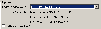
When changing the logger device family, beware that they are not 100% compatible.
For example, the CAN logger inside the "MKT-View I" can filter out a maximum
of 48 different CAN messages from the stream, while the "MKT-View II" supports
a maximum of 128 (or even more). So when switching the device family from
"MKT-View II" to "MKT-View I", some message- and/or signal definitions may
get lost.
Because the CAN logger was primarily intended to log
CAN-SIGNALS(*), you must select
these signals on a special tab of the utility:
(screenshot CANdb tab)
On the CANdb tab, you can
-
Select messages or signals from CANdb files (which can be loaded via the
File menu)
-
Add or remove signals from the list of "logged" signals
-
Rearrange the sequenze of logged signals (the buttons with blue arrows mean
"move up" / "move down")
-
See some information about a logged signal, including the CAN-ID and some
mapping parameters
To import ("load") a CANdb file, use the file menu. If you have used a certain
CANdb file earlier, you will find it in the "Most recent CANdb file" list
- which is quite handy because this way you don't have to remember the full
path name, and it may save a dozen mouseclicks in the file selector box.
To select signals from a loaded CANdb file, you can use..
-
a tree view (as shown in the screenshot)
-
a table view (which contains ALL information about the loaded signals)
-
a group of three lists (NODES, MESSAGES, SIGNALS)
To copy a signal from the tree
view, you can drag it with the mouse and drop it into the list of
logged signals. The same is possible with entire messages (containing multiple
signals), nodes (containing multiple messages), or CAN buses (containing
multiple nodes). You may get a warning if duplicate signal names are already
present in the list of logged signals (in the right part of the window).
Avoid duplicate signal names in your CAN databases whereever possible.
Alternatively, you can select an item in the table view and then
click the "Add signal(s) to list" button.
The list of logged signals will be saved as part of the logger configuration
file. The CANdb file will never be modified because the CAN logger configuration
utility is not a CANdb-editor !
You can use up to four of the logged signals as
trigger signals.
-
(*)footnote:
-
Apart from selecting logged signals from a CANdb file, it
is possible to..
To simplify the selection of signals from large databases, there is a
search function for signal names. You can enter a search pattern
in the edit field close to the "Search"-button, and press ENTER after that
(or click the search button). The search pattern may contain the following
wildcard characters:
-
? Placeholder for "any single character (letter or digit)
-
* Placeholder for a whole group of characters. Must not be used at
the 1st position in the string !
Search pattern examples:
-
Thermo searches all signals named "Thermo", in all messages, on all CAN buses,
sent by any node in the network.
-
A* searches all signals beginning with 'A'
-
?bc* searches all signals with 2nd letter = 'b', 3rd letter = 'c', and an
unknown number of letters afterwards
The properties of any logged signal can be displayed in the "Signal Info"
box. It is in the lower right corner of the signal definition tab. The contents
of this editor-like window may look like this:
| Display (example) |
Explanation |
| PrintedChars |
Signal name |
| id=0x0000007B |
CAN id (+ explanation of the most significant bits 31..29 if set) |
| node="Terminal" |
name of the sending node |
| msg="MuxedMsg" |
name of message containing this signal |
| mapping=(8,8,I,U) |
mapping info: position of LSBit, number of data bits,
byte order: Intel/Motorola,
data type: Signed/Unsigned/Float/Double |
| MuxVal=#0, MuxMap=(0,8,I) |
Only if multiplexed : multiplexor value, multiplexor mapping (see above) |
To see the properties of the logged signal, select it in the list of logged
signals.
Additionally, you can check the CAN message layout in graphical form as explained
in the next chapter .
The layout of a logged CAN message can be displayed in graphical form. This
may be handy when problems with the interpretation of different bit-counting
schemes occurr (for example, "Intel-format", "Motorola forward", "Motorola
backwards" and other oddities).
The graphic shown on the left shows an example of a CAN-message which carries
various signals. The currently selected signal is marked with a bold arrow,
and its name is displayed at the bottom of the window. The arrow always points
from the least significant bit (LSB at the end) to the most significant bit
(MSB at the arrow head).
The bit numbers within a data byte are listed at the top of the display.
Please note that -as usually for binary numbers- the most significant databit
is on the left side; the numbers for 8 bits within a byte always runs from
0 (=LSB, right) to 7 (=MSB, left).
Within the 64 bit of a CAN data field, the bit count runs as shown in the
diagram: The first byte [0] containts bits 7 to 0; the last byte [7] contains
bits 63 to 56. It doesn't matter if the CAN message contains signals in Motorola-
oder/and Intel-Format ! (Caution, some CANdb-editors count bits in a different
fashion, but of course this must not change the physical position of a bit
within the CAN frame).
If the selected signal is multiplexed (as shown here in the example), not
only the signal's data bits, but also the multiplexer for
this signal will be shown (using the same colour, but hatched). The values
of the multiplexer-bits will also be displayed (since the multiplexer value
is a constant which identifies this signal).
-
Note:
-
The multiplexer/multiplexor is also called "mode signal" in other
documents, but this name is rather meaningless so we avoid it.
To select other signals in the displayed message, click into the diagram
with the left mouse button.
Contents
This tab of the Logger Configuration Tool contains a list of the CAN messages
which shall be logged (and some other specialities too).
The lower part of this tab contains a table for "other" logged values, which
will be explained in one of the next chapters.
But first look at the upper table. It contains a list of all
messages which shall be logged.
There is one row in this table for every CAN-message. The
columns in this table are:
-
Nr
This index references the message. It runs from zero to the maximum number
of logged messages.
-
Bus
1 = "Message shall be received from Bus 1 (the first CAN interface)"
2 = "Message shall be received from Bus 2 (the second CAN interface, if
available)"
-
CAN-ID
CAN message identifier in hexadecimal notation. "0x" is the prefix for a
hex number. 11-bit ID's contain three hex digits, 29-bit-ID's eight digits.
-
Message Name
Usually copied from the CANdb-file, in the moment when you added CAN signal(s)
as explained in the previous chapter. For self-defined CAN messages, you
may type short descriptive names, without space characters and other special
characters (only letters and underscores).
-
Sender (Node)
Identifies the sender (the sending "node") of this message. Remember, one
node can send more than one message. Like the message name, this name
originates from the CANdb-file.
-
Intv.-Limit (write-interval
limit)
In this column you can define a message-specific limitation for the write interval
in the logger. For example, a message may be transmitted on the CAN bus
every millisecond, but you only want the logger to write this message
to the memory card every 200 milliseconds. In that case, type "200" into the
Interval-Limit column for this particular message.
Zero means "there is no individual writing interval limit for this
message".
Note: There is also a common write-interval limit for
all messages
(and for logging 'other' data) on the logger configuration tab.
Usually this table will be filled automatically when you
select signals for logging. To add entries
manually (because you have no CANdb file to select signals from), look
here.
Contents
Switch to the "Logger Configuration" tab of the utility. You will see the
current settings in several edit fields, check boxes, combo lists etc. Modify
them for your needs and save the modified configuration (the tool will ask
you upon exit if you want to save the changes, if any).
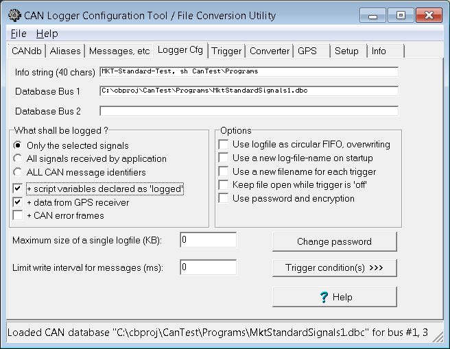
(screenshot "logger configuration" tab)
The controls on this tab are:
-
Info string
A string of up to 40 characters which can be displayed on the terminal screen,
using the interpreter function "logger.info" .
The upper part of the panel titled "What shall be logged ?" contains three radio buttons (only ONE option can
be selected at a time) :
-
Only the selected messages/signals
The logger only writes the signals into the logfile, which you selected on
the CANdb (or "No CANdb") tab.
-
All signals received by the application
The logger only writes those signals into the logfile, which are received
by the terminal application. The advantage is, you don't
have to produce an extra configuration for every new application of the terminal.
Instead, you log all messages which are handled (received) by the terminal.
-
Receive
and log ALL CAN messages
Useful to analyze the complete CAN bus traffic. This only makes sense if
you export a message list later, not a signal list !
Caution #1 : This option cannot be used together with the option "Limit write
interval for messages" ! Explanation:
see appendix.
Caution #2 : As a matter of course, CAN logfiles can only be converted (decoded)
into physical signals, if the required signal decoding- and scaling information
is available to the logfile converter ! Setting the option "Receive and log
ALL CAN messages" alone (without adding the required signal definitions from
the CAN database) is not sufficient to export decoded signals (not messages)
later. Also see the notes on the logfile converter, option
"Ignore Signal Definitions
from Logfile, use currently loaded signal definitions instead" .
The lower part of the "What shall be logged ?" panel allows to select some other data
(which are not related with normal CAN messages):
Group "Options":
-
Use logfile as circular FIFO, overwrite old data
If this option is set, the opened logfile will work like a FIFO buffer, which
wraps to the start of the file when the maximum file- or disk-space is exceeded.
In other words, if the logfile is "full", the writing-position will jump
back to the begin of the file, and the oldest entries are overwritten. When
the logfile is closed, only the "newest" data are in it - how many, depends
on the maximum file- or disk size.
If this option is not set, old data in the logfile are
not overwritten. Instead, when the file size is reached,
a NEW logfile will be created as explained below (under "maximum size of
a single logfile").
Note: This has not got anything to do with the
pretrigger . The pretrigger memory is always a
RAM buffer, to avoid unnecessary wear of the FLASH memory card, as long as
no "interesting" data are received !
-
Use a new logfile on startup
If this option is set, the logger will use a new filename (with incremented
index) on system start. In other words, a new file for each time you turn
the power on.
Otherwise the logger firmware will try to re-open an already existing file
on system start, and append new data to that file. This option is usually
combined with the option "use file as FIFO". Please note that high-resolution
time channels in the logfile may be not monotonously rising
without this option, as explained here
.
-
Use a new filename for each trigger event
Similar as above. If this option is selected, the logger will use a new filename
whenever the trigger switches from "OFF" to "ON".
Without this option, multiple trigger cycles (trigger ON -> trigger OFF
-> trigger ON) will be recorded in a single file.
-
Keep logfile open
With this option, a logfile will be kept open even if the trigger stops a
recording. This is a bit faster, especially when combined with the pretrigger
option.
Without this option, the logfile will be closed immediately if the trigger
stops a recording, and re-opened when restarted. Use this option if the logger
will be mostly "not triggered", because it reduces the risk of data loss
if the power breaks down by accident (see notes on the
power supply ).
-
Use password and encryption
You may encrypt the logger configuration file and the header section of the
logfile to protect the CAN configuration data. Some user's were not happy
about the ASCII files. If a password is used, the letters and digits in these
files will be scrambled.
Other options..
- Maximum size of a single logfile
A value of zero means "unlimited file size" (only limited by the capacity
of the memory card). Non-zero means the maximum size of a single logfile
shall be limited - usually to a few Megabytes. If the filesize is reached,
the behaviour of the logger depends on the option "Use logfile as circular
FIFO" (explained above). Without this option, the current logfile is
closed and a new file with a different name (increased sequence number in
the last two letters of the filename, for example canlog00.cld, canlog01.cld,
canlog02.cld). This is helpful when you only need to copy a part of the logged
data to your PC. A 500-MByte-monster takes a some time for copying, even
with a fast memory card reader on the USB port - and even longer if you
want to send it to someone via email for examination.
- Limit write interval for messages (and other data)
If you already know that you don't need millisecond-resolution for the logged
data before starting a logging session, limit the write interval
for messages here (in the logger configuration). This will reduce the size
on the flash memory card, and reduce the CPU load of the CAN logger itself,
and will make the conversion of the logfiles into some other formats faster.
See also: write interval of
the CAN logfile converter.
The same parameter is also used as the recording interval (inverse of the sampling rate)
for 'other data', for example
calculated numeric expressions
or logged script variables.
Notes:
- This option has no effect on CAN messages when used together
with the option "Receive and log ALL CAN message identifiers" ! Reason / explanation:
see appendix.
- There is also an individual
write-interval-limiter for certain CAN messages on the "Messages" tab.
Note: The trigger conditions and
trigger options are configured on other
tabsheets !
The CAN logger is controlled by a state machine which can be checked with
the function logger.state (if the CAN logger is part of a
programmable terminal):
The logger states
are:
Stopped
(or "off")
-
The logger (!) is passive and does not consume significant CPU power
-
Messages are not placed in the log buffer
-
The logfiles on the flash memory card are closed
-
The trigger condition are not monitored (because messages are not handled
in this state). This saves a large amount of CPU power !
Engaged
-
The logger function is active and analyses all received CAN messages. The
CPU load is already higher than in the stopped state.
-
Logfiles on the flash memory card are already opened, and -if the file is
used as a giant FIFO- new entries may already be written to the file.
-
The trigger conditions are permanently monitored to detect a possible "start"
condition. If a START condition is detected, the logger switches from
enaged to triggered.
Triggered
-
The logger function is active and analyses all received CAN messages. The
CPU load is even higher than in the engaged state.
-
Received messages are written from a RAM buffer to the memory card.
-
The trigger conditions are still monitored to detect a possible "stop" condition.
If a STOP condition is detected while the START condition if
false, the logger switches from triggered to
engaged state (but not to stopped !).
-
Note: the post-trigger phase is almost the same
as the 'triggered'. The only difference is the value returned by the
logger.state function of the
interpreter.
The initial logger state after power-on can is defined on the
Trigger Option tab ("triggered by default"
etc).
The transitions between the logger states are either initiated
by the logger itself, depending on the trigger conditions, or with an interpreter
command. A complete list of logger control commands is in the
manual of the terminal programming
tool. Here just a few of those commands :
-
logger.run
-
Activates the CAN logger, but does not necessarily trigger it
(depending on the configuration). Switches from stopped to
engaged, but not from triggered to engaged. If the firmware
refuses to switch into the engaged state, there may be something wrong with
the memory card.
-
logger.stop
-
Stops the CAN logger. The logfile on the memory card is closed, so you can
safely remove the card. No popup window appears (in contrast to the 'card.remove'
command. In the stopped state, the trigger condition is not permanently checked
in every received CAN message, which saves a large amount of CPU power !
-
logger.trigger(X)
-
Triggers a recording (X=1) or clears the trigger flag (X=0). Does not close
the logfile. Intention: Manual trigger or trigger by the user-programmable
terminal application. Examples:
logger.trigger(1) : rem Start recording to the CF card
logger.trigger=1 : rem Same effect as above, only different
syntax
logger.trigger=0 : rem Stop recording, but keep buffering received
frames
If the firmware refuses to write data to the memory card, the reason may
be power=0 (power-good flag not set).
Note about "logger.run" vs "logger.trigger":
Setting the trigger (=begin writing to the logfile) with this command
automatically includes activating the logger (logger.run). But,
if the logger was not running when executing the trigger-command, there will
be nothing in the pretrigger-buffer.
So, if you need
pretrigger-data, activate the
logger before triggering it !
-
logger.state
-
Returns the current state of the CAN logger as a numeric value. Possible
results :
0 = "stopped" (file not open, or buffer not filled in interrupt, possibly
a problem with the memory card)
1 = "engaged" (file open, ISR active, but not triggered yet)
2 = "triggered" (file open, ISR active, AND "triggered" )
3 = "post-trigger" (after "triggered"). Only occurrs if the
post-trigger time in the logger configuration
is non-zero.
Notes:
-
You don't have to use these interpreter commands to controll the logger's
trigger ! Usually, the logger works silently in the background, and you don't
have to care for it when programming your terminal application. The logger
control commands have only been implemented for 'very special cases', when
the built-in trigger possibilities are not sufficient.
-
There are some other interpreter commands to control the logger, and to check
the memory card, explained in the
manual of the terminal programming
tool. Such commands include: card.insert, card.remove, card.dspace (retrieve
free disk space in kByte)
Pretrigger
You may be interested in the history of the logged signals a short while
*before* the trigger event. This is possible, because the logger records
the most recent message in a RAM buffer even if the logger is not in the
'triggered' state. By setting the pretrigger-field to a value greater than
zero (seconds), a part of the messages in the RAM buffer will be flushed
to the logfile when the trigger start condition becomes TRUE.
Note: Depending on the size of the RAM buffer, and the average message rate
on the CAN bus, the logger firmware may not be able to save as much 'seconds
of pretrigger data' as you want. The buffer capacity which is available for
pretriggering is roughly 3000 messages.
The pretrigger interval is defined on the
'trigger options' tab.
Posttrigger
To record a few seconds *after* the trigger condition became FALSE (and/or
the stop condition became TRUE), set the posttrigger-field to a value greater
than zero (0 means "no post-trigger"). Usually, recording to the logfile
stops 0...10 milliseconds after the trigger is stopped. With the posttrigger
option, you can record some additional seconds. The posttrigger's internal
function is very different from the pretrigger, there is no limitation due
to the RAM buffer size for the posttrigger (the maximum is 327.67 seconds
of post-trigger data).
The posttrigger interval is defined on the
'trigger options' tab.
This chapter only applies to the older "MKT-View I" with 16-bit CPU !
If you are using the "MKT-View II" (with 32-bit CPU), use the
Trigger Condition Grid as explained
in the next chapter instead !
In the MKT-View I, you can use up to four signals as trigger sources. The
trigger condition tab may look like this:
(screenshot "trigger conditions", blue marks explained below)
The components of a trigger definition are:
-
1 = Trigger Signal (source)
-
The list in this combo box contains a list of all possible trigger sources.
If the list is empty: see notes
below.
-
2 = Compare Operator
-
Possible comparisons are: <, >, <=, >=
-
3 = Comparation Value
-
Enter a numeric constant here. The format is the signal's scaled value.
But caution:
Internally, the trigger operates on RAW CAN VALUES. So avoid values which
don't exist on the CAN bus, for example 0.5 if the signal is a one-bit-value
which can only be 0 or 1.
-
4 = Inner boolean combination
-
The two comparations can be logically AND - or OR -combined.
-
5 = Outer boolean combination
-
Defines how the two conditions shall be combined. For example, logging may
start when BOTH conditions are true ("AND"), or when ANY of the conditions
is true ("OR"). If you do not need the second conditional term, set the outer
combination to "--".
Usually, there is a trigger START condition and a trigger STOP condition.
If you don't need a STOP condition, you can use lines 5...8 of the trigger
condition as an additional set of START conditions.
There are four trigger sources, which must be connected to SIGNALS. The combo
boxes are filled with the list of logged CAN SIGNALS. If these
lists are empty,
you must import some logged signals on the CANdb
import tab before you can define the trigger conditions !
Notes:
-
You don't have to use all these trigger conditions. Set unused trigger signals
to "--unused--" in the trigger signal selectors
(1) . If only one trigger condition is used
(like
Thermo1 < 1.1), you don't need the logical combinations.
You don't even need a single trigger condition if you set the initial
trigger state on the logger configuration tab to
"triggered".
-
The logical AND combination returns TRUE if both inputs are
TRUE, and returns FALSE in all other cases. If comparation operators or
comparation values are improperly selected, an AND combination may NEVER
return "TRUE", for example "(X<7) AND (X>8)". The utility tries to
check such conditions and shows a warning if this may happen.
-
The logic OR combination returns TRUE if any of the two inputs
is TRUE, and returns FALSE only if both inputs are FALSE. If comparation
operators or comparation values are improperly selected, an OR combination
may ALWAYS return "TRUE", for example "(X<8) OR (X>7)". The utility
tries to check such conditions and shows a warning if this may happen.
-
If both START- and STOP condition are TRUE at the same time, the logger will
be triggered. If either START nor STOP are TRUE, the
logger state is not changed.
The trigger input works as explained in the following
circuit schematics. The trigger is, of course,
realized with a piece of microcontroller firmware instead of logic gates.
Each of the four trigger input variables (V1...V4) is compared against two
constants (C1...C8). The comparator results can be selected individually
for 'less than' (<), 'less or equal' (<=), 'greater' (>) or 'greater
or equal' (>=) with the comparator output switches CO1...CO2.
In the next stage, the comparator outputs are combined in two stages, each
selectable for logical AND or OR combination. The combined results are labeled
Start and Stop signal in the above diagram. They
are the inputs into a Set/Reset flipflop with the following truth table:
| START |
STOP |
new trigger state |
| 0 |
0 |
NO CHANGE |
| 0 |
1 |
untriggered (engaged) |
| 1 |
0 |
triggered |
| 1 |
1 |
triggered (!) |
Usually, the logger operates in a state-triggered mode (as shown
in the truth table). Alternatively, it can be set to
edge-triggered mode as shown in the
next chapter.
Note that if both START and STOP condition are TRUE (1) at the same time,
the logger will be triggered !
This chapter only applies to the newer "MKT-View II" with 32-bit CPU (ARM-7) !
If you are using the older "MKT-View I" (with 16-bit CPU), use the
Trigger Condition Tab as explained in
the previous chapter instead !
The MKT-View II allows the definition of up to ten (?) trigger signals. Each
of these trigger signals can be used either as START- or as STOP-condition.
In contrast to the older MKT-View I, the trigger signals are defined in a
table ("grid") as shown below.
Note: Before you can select trigger signals, you must import at least one
CANdb file, and select all ignals which shall be logged.
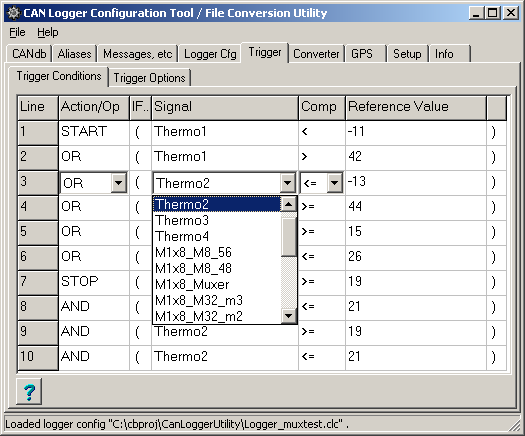
The columns in the trigger definition table are ..
-
Line : line number, running from 1 to 10 if ten different trigger sources
are supported.
-
Action/Op (Action or logic operator)
START : This line is the begin of a new START-conditon
STOP: This line is the begin of a new STOP-conditon
OR : This line contains a sub-expression which will be logically ORed to
the previous line
AND: This line contains a sub-expression which will be logically ANDed to
the previous line
Note:
-
In this trigger definition table, there are no different prioritities for
AND / OR, in contrast to programming languages like "C" and Java. The logical
combination is always evaluated in the sequence of the table (i.e. evaluated
from top to bottom).
-
If there is no STOP condition in the table at all, the logger uses the inverted
START condition as STOP.
-
IF.. : The opening parenthesis in this column marks the begin of a comparison
between the trigger signal and a reference value.
You can read the table like: "START IF ( Thermo1 less than -11 degrees )
OR IF ( Thermo1 greater than +42 degrees celsius)"
-
Signal : Name of the trigger signal (received from the CAN bus).
To select a signal, click into the field to open a combo box. All signals
which can be used as trigger source are listed in the combo, and -possibly-
some other sources which are *not* CAN signals.
-
Comp (Comparator) : Comparison operator, can be either
"<" (less than), "<=" (less or equal), ">" (greater than), ">="
(greater or equal).
In addition (only for MKT-View II with firmware date 2009-01-08 or
later) :
"==" (equal), "!=" (not equal), "&" (bitwise AND, here: used as
bit-test-operation)
-
Reference Value : The trigger signal will be permanently compared with this
value .
(At the time of this writing, the reference value had to be a
constant. This may(!) change in future versions of the MKT-View
II firmware)
Hint: You can check the actual state of the trigger signals during operation
on the "MKT-View II". To do this, enter the terminal's
system menu, or open the shutdown screen. Select
"CAN-Logger" or "CAN logger config", "Trigger Settings"..."Show Trigger
Conditions". You will see all trigger signals (in the same order as in the
table shown above), along with the signal names, the current signal values
(column "SigValue", if the signal has been received since we started), and
the result of the comparison in each line :
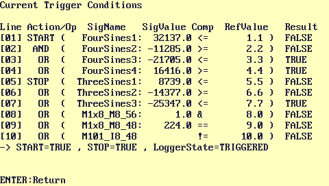
The screen also shows the combined start- and stop conditions, and
the current state of the logger (passive / enaged / triggered / post-trigger
).
< under development ... more coming soon ... ;-) >
The following TRIGGER options can be defined on this tabsheet of the Logger
Configuration Utility :
-
Initial trigger
state
Defines the initial state of the logger's trigger, as described in the chapter
The Trigger State Machine.
When set to "Triggered", logging starts immediately after the terminal is
powered on (as if the trigger condition was "immediately TRUE"). Otherwise,
logging starts when the condition defined on the
trigger condition tab gets TRUE.
-
Pretrigger (seconds)
Define how many seconds of logdata you want to have recorded BEFORE the trigger
event. Note that there may be less than the desired pretrigger size, depending
on the CAN message rate and the size of the internal buffer (approximately
3000 messages can be buffered internally, so don't expect too much pretrigger
data if there are 2000 messages per second in your network !). A value of
zero means "no pre-trigger".
-
Post-trigger
(seconds)
Define how many seconds of logdata shall be written AFTER the trigger stop
condition has been detected. Up to 327 seconds of post-trigger data are possible.
A value of zero means "no post-trigger".
-
trigger on RISING EDGE of start-conditions
Set this checkmark if you to trigger on the rising edge of the trigger
start condition(*). This means, trigger only if the
start condition changes from FALSE to TRUE. If this mark is unchecked, the
CAN logger will operate in state-triggered mode.
-
trigger on FALLING EDGE of start-conditions
Trigger recording if the start condition changes from TRUE
to FALSE . Can be combined with the previous option to trigger on both slopes
(rising+falling).
-
stop on RISING EDGE of stop-conditions
Stop logging if the stop condition changes from FALSE to TRUE . Without this
option, the stop condition works in state-triggered mode.
-
stop on FALLING EDGE of stop-conditions
Stop logging if the stop condition changes from TRUE to FALSE . Can be combined
with the previous option to trigger on both slopes .
-
Pre- and post-trigger phase only (time-limited recording)
Should be used in edge-triggered mode only. The logfile will only consist
of a few seconds of pre-trigger data, and a limited interval of post-trigger
data, but nothing in between. For example, use this option to trigger on
a signal which changes from "low" to "high", and then stays "high" forever,
but you only need a recording of a few seconds before and after the low-high
transition. The number of seconds before the transition is the
pretrigger interval, the recording time
after the transition is the post-trigger
interval.
Below is an example for edge-triggered logging, with a time-limited recoring
consisting of 10 seconds before the trigger (pre-trigger), and 20 seconds
after the trigger (post-trigger) :
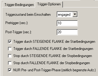
(Example for an edge-triggered configuration, with time-limited recording
for each new event)
(*) Note: "Rising" / "Falling" edge applies to the trigger-start-condition
(TRUE/FALSE), not to the physical value of the trigger signal itself ! If
you don't understand this little but important difference, look at the
trigger block diagram again. The trigger signals
are on the left side, the trigger conditions are the outputs labelled "Start"
and "Stop".
You can, if requrired, also log other CAN messages which are not defined
in a CANdb file. You may use this as a makeshift solution if there is no
CANdb file available at all.
The contents of this table were explained in a previous chapter - if you
missed it, click here .
Note: The messages defined this way cannot be 'decoded' into signals ! So
defining your own messages here only makes sense if you want to have a listing
of CAN messages (no signals) and their data in hexadecimal
form. Defining own signals is not possible with this tool - use an external
CANdb editor for that task ! There are some very
nice CANdb editors around, for example by Vector or Kvaser which can be used
to create your own CAN database.
Certain terminals (like "MKT-View") have a built-in NMEA-decoder, which allows
them to decode data from a GPS receiver. If that function is available, the
GPS data can be logged together with the other data. Of course, you need
a suited GPS receiver with an RS-232 interface (often called "GPS mouse")
for this job. Furthermore, if the GPS receiver needs some special initialisation
sequence to start, make sure you configure it correctly (this can be done
with the display program, using the "gps"-commands which are not scope of
this document). Just an example, usually located in the event definitions
on page 0:
gps.baud=9600 : gps.prot="NMEA" :
gps.cfg=1 : rem Init GPS-mouse, 1 Hz
To record GPS data with the CAN logger, set the checkmark "Log data from
GPS receiver" on the logger configuration panel.
This flag will be saved as part of the logger configuration file (logger.clc).
Alternatively, you can turn GPS logging on or off in the terminal's system menu
(select "CAN logger config" ... "Buffer/Mode settings" ... "Record GPS (nav) data",
and set the parameter value to TRUE or FALSE. Don't forget to save the modified
configuration after that ! ).
To define how the GPS data shall be converted into other files later, there
is a special tabsheet named "GPS" in the
CAN logfile converter.
In addition to logging CAN messages, the logger in the MKT-View terminal
may also log some other data. For this purpose, you may enter up to eight
numeric expressions in the table shown below.
These expressions will be evaluated once per write interval (if
there is no write interval specified, once every 100 milliseconds).
The same table is (internally) also used to log script variables, more on that later.
Remember that built-in functions always begin with a lower case letter,
user-defined display variables must begin with an upper-case letter !
More information about numerical expressions can be found in the manual for the
terminal programming tool.
The definition table for numeric expressions is on the lower part of the "Messages, etc" tab of
the CAN logger configuration utility. In the example, the following values
are logged: The first analog input (ain1), the terminal's supply voltage
( sys.vsup, here scaled into Volts), the terminal's internal temperature
(sys.temp, here in degrees Celsius), the current page number (pn), and the
count of "lost" messages (logger.lost). These values will be added in extra
columns of the converted logfile. If no name is specified in the table, the
expressions themselves will be used as column names - which may cause problems
in the exported ASCII file if the expression contains the
column separator character.
The min- and max values are only used for the graphic preview window. The
values actually recorded and exported will *not* be limited to this
range !
Notes: Because evaluating these expressions with the interpreter may be quite
time-consuming, it makes no sense to use sampling intervals below 100
milliseconds. Logging the interpreted results only makes sense if the
output type for the logfile converter
is set to Signals (not Messages !).
Since January 2014, it is possible to log script variables along with the CAN traffic.
To achieve that, ...
- the to-be-logged script variables must be declared (in the script) with the 'logged:' attribute;
- the option add script variables declared as 'logged' must be set on the panel titled 'What shall be logged';
- there must be sufficient space left in the table with 'numeric expressions' shown above
- the sampling rate (inverse of the write interval) must be set to a meaningful and realistic value
After reading the logger configuration file, the device firmware will automatically append the names
of all SCRIPT VARIABLES declared with the 'logged' attribute as 'numeric expressions'
(after those entries which you possibly entered yourself, manually, in that table).
It's not necessary (and not possible!) to enter the names of script variables
in the table shown above - it's enough to declare them as 'logged' in the script sourcecode.
The sampling rate for those script variables is the same as for the other rows in the 'NUMERIC EXPRESSIONS',
defined as write interval (limit) on the Logger Configuration tab.
See also: Script language manual (pdf, online) .
After all logged signals are defined, and the logger configuration -including
the trigger settings- is finished, you must save the CAN Logger Configuration
file (*.CLC) on a Compact Flash Memory Card because this is the only way
to transfer the configuration into the logger hardware. On the memory card
which will be used in the logger later, the configuration file must have
the name LOGGER.CLC because only this file will be read automatically from
the Compact Flash Memory Card when the logger is powered up.
To achieve this almost "automatically", you can set the tool's default directory
on the Settings tab so the logfile will be automatically be
written to the memory card (if you have a suitable
memory card reader / writer installed
in your PC). The next chapter will show you how.
If the configuration has been changed, the program will ask if you want to
save the modified configuration in a file. If you have the memory card in
the drive at that time, click "Yes" and the new configuration will be written
to the memory card without further questions.
On the Settings tab of the logger utility, you can define the
default directories for some frequently used file types :
(screenshot "directories")
Note: On the author's PC, drive "I:\" is the memory card's drive. This will
be different on your PC !
To modify the file- or directory names, you can either type the name in the
edit field or click on the "..." button to its right to open a selection
dialog. The following fields can be modified in the Directories group :
-
CAN log files
-
This is the default directory for logfiles. You may set this to your CompactFlash
card drive, but often the file conversion runs faster if you copy the logfiles
from the memory card to your local harddisk before converting them (especially
if these files are very large !)
-
Logger
config
-
The name and location of the CAN logger configuration file. For your convenience,
select your memory card drive here, and use the filename LOGGER.CFG because
this file will by loaded into the logger automatically during power-up.
-
CANdb files
-
This is the default directory for importing CANdb files
-
Exported
-
This is the directory where the converted files are written to ("exported").
back to top
The CAN Logger can be used in two basic modes:
-
Log 'all received messages', no matter how frequently they are received.
Advantage: Message timing and frame rates can be reconstructed later
Disadvantage: Unpredictable logging capacity in terms of recording time.
Danger of system overload.
-
Log the 'latest received messages' with a limited recording interval.
Advantage: You know how many hours of data can be logged. System overload
is unlikely.
Disadvantage: Cannot see the run of the curve in between the recording
intervals
The messages which shall be logged can be selected with the Logger Configuration
Utility (as already described in another
chapter). The signals which shall be logged may be selected from
a CANdb file. The Logger Configuration Utility produces a configuration file
for the logger, which will be loaded by the logger during initialisation.
The following steps must be performed for a complete configuration / logging
/ analysis - cycle:
-
Produce a logger configuration file as explained
here . This includes selecting what you
want to log , and how to log the data !
-
Copy the logger configuration file to a Compact Flash Memory Card
(or save it directly on the card from the logger
configuration utility)
-
Turn the CAN logger off (obey the proper power-down sequence)
-
Insert the memory card in the logger's CF memory card slot
-
Connect the logger with the CAN bus which you want to analyze
-
Turn the CAN logger on
-
Set "power=1" in your terminal program (via
interpreter, when the supply voltage is REALLY safe).
-
Let the logger log (triggered or untriggered)
-
Set "power=0" if there is the risk that someone
cuts off both supply voltages simultaneously
-
Turn the CAN logger off (obeying the proper power-down sequence !)
-
Remove the memory card from the logger and insert it in your PC's card reader
-
Start the logfile converter as explained
later
-
Load the converted files into an analysis tool of your choice
The logger configuration is saved in a small textfile named
LOGGER.CLC (CLC = Can Logger Configuration), which must
be placed in the root directory of the memory card. Usually this file will
be created and modified by the Logger Tool; in other words the file
LOGGER.CLC is the connection between the tool and the
logger itself. It's usually a one-way-street: The
CAN-Logger-Configuration-Utility writes this file, the CAN-Logger
(hardware) only reads the CLC-file !
While the logger is active, it usually waits for the
trigger condition, and -once triggered-
records the selected messages in a file with the extension CLD (Can Logger
Data). When logging is stopped, the file is closed. When a new trigger condition
occurrs, a new CLD file may be written (the old data are not lost). To remove
the card from the logger, you must either turn the logger off, or invoke
a firmware command to close the logfile. Otherwise you would damage the data
on the card (directory or FAT). If this happens by mistake, you must run
the program SCANDISK to repair the card's file system.
The logged file(s) can be converted with the logger tool into various other
file formats, which will contain the decoded signal values (not the raw CAN
messages). These files can then be loaded into other programs like
Excel™,
DIAdem™, and some other programs too.
Alternatively, the logfiles can be converted into
Vector™ ASCII CAN logfiles, which -for
example- can be played back into the CAN network in the laboratory for testing
purposes. MKT's own CAN-bus-tester can do this too.
The supply voltage of first hardware versions of the MKT view terminal (I,
not II) was specified 9 to 36 Volts,
for both "switched" and "standby" voltage. As mentioned in the hardware manual,
the standby voltage is required to shut the terminal down properly, including
closing all open files which very important to keep the CF memory card's
directory structure and file allocation table in order.
Caution: While data are been read from or written to the memory
card,
it must not be removed from the device, and the device must not be turned
off.
On some devices (for example, terminals with SD-/MMC-cards)
a red LED near the card slot signals this state.
Ignoring this rule may damage data on the card.
Backup your data wherever possible !
MKT Systemtechnik will not accept responsibility for any data loss
or loss directly or indirectly caused by data loss. |
A problem arose when the terminal was used in passenger cars with 12 Volt
power supply, when both (switched + standby) voltages were fed by the same
battery. When starting the engine, the battery voltage dropped to 6 Volts
which is not sufficient for the terminal. When, in this condition, a logfile
was open, the data on the card were corrupted (destruction of FAT and/or
wrong directory entries).
Note: If there was an illegal / unexpected power shutdown, the terminal will
show the following message when turned on again:
SOS - Device has NOT been shut down
properly, maybe supply voltages
are connected in parallel ?
THIS MAY DAMAGE THE MEMORY CARD !
USE MS-"SCANDISK"(*) TO REPAIR IT ! |
(*) The program SCANDISK was used under Win 98.
Under Win XP, it doesn't exist any longer;
use CHKDSK or a similar utility in that case.
To relax this hardware problem via software, the flash memory card is disabled
for any WRITE-access until your terminal application sets the "power good"
flag. This can be done with the following interpreter command:
-
power=1
-
This command means "The power supply is safe now, there is no risk of losing
both supply voltages at the same time".
You may use it in an event definition, triggered -for example- by a comparison
of the engine revolution speed. If the motor runs at 1000 RPM or more, set
power=1 . If you cannot access the motor's RPM value via CAN, use a
hotkey to set "power=1" - with the disadvantage that it will be the operator's
responsibility to press the button only AFTER starting the engine.
-
power=0
-
This command means "The power supply is unsafe now, there is the risk that
both supply voltages will fail at the same time".
You may use it in an event definition, triggered -for example- if the motor
runs at 500 RPM or less.
Setting "power=0" disables write accesses to the CF memory card. This will
cause the terminal to close all files which were opened for writing, including
the logfile, etc.
For testing or 'diagnostic' purposes, you can read the state of the power-good
flag like an ordinary variable. But remember, it is YOUR task to keep this
flag up-to-date.
The default state of 'power' is zero, which means power is unsafe, and writing
to the CF memory card is impossible. In a future redesign of the terminal
hardware, this may change. If the terminal runs properly at 6 Volts (or less),
we may modify the firmware so the power-good flag will be '1' by default.
In the sample terminal application "LogDemo1.cvt" (distributed with the terminal
programming tool), you will find an example for the usage of the power-good
flag. In the simple example, the user is asked to "press any key" as soon
as he thinks the power is safe, and to press the F1 key later before turning
the engine off. As explained above, you may replace this with a more
sophisticated solution, using the engine's revolution speed to set power=0
or power=1.
The problems mentioned above do not apply to the
MKT-View II (with ARM-CPU, available since
2008). The MKT-View II has an internal backup-capacitor, which can provide
the power for a few seconds after removal of the external supply voltage.
So the CPU can savely power down the memory card, even if all external voltages
are removed. For compatibility reasons, the power-flag still exists
in the MKT-View II, but it is automatically set to TRUE as soon as the backup
capacitor is fully charged (which takes a few seconds after power-on).
back to top
Note: This document describes a work in progress. The
finally released version may look different !
To convert a logfile from the CAN logger into some format, use the "File
Converter" tab of the CAN logger utility. If you double-click on a *.cld
file (CAN Logger Data file), this tab will be opened automatically.
The list on the left side contains the names of all files which shall be
converted. With the Select files button, you can add more files
to the list. Alternatively, you can add logfiles (*.cld) from an explorer
window via drag- and drop.
The fields in the Destination box describe the format of the
output file. The settings in this box depend on the program used for
post-processing (for example: spreadsheets, data visualization tools, statistic
evaluation programs). You will only have to adjust these settings once, because
they are saved permanently in a special configuration file (not in the
logger configuration file !).
To start the conversion, click on the Go! button. The name of
destination file will be automatically produced by the tool, matching the
input file but using a different extension; it is displayed on the bottom
of the File Converter tab.
The conversion parameters are:
-
Output
Type
-
Signals: Write signals, not CAN messages into the output files.
All signals which are contained in the logfile are decoded, the results are
written into the output file.
Messages: Do not decode the messages from the logfile, instead
write the CAN message frames in hexadecimal form (one frame per text line).
Though this mode may sound exotic : it fulfils the function of a true CAN
LOGGER !
-
Output file format
-
An awful number of different output file formats had to be implemented for
various users, here just a few...
-
-
Text
-
A plain textfile ("ASCII") which can be viewed with any text editor, or imported
into many spreadsheet programs.
You must define the separator characters for the text ouput format in a few
other edit fields, see below.
-
CSV, international
-
Comma Separated Values. Can be imported into many spreadsheets on a PC with
an english windows installation
-
"CSV", german
-
This 'nationale' CSV-variety can use a comma instead of the decimal point.
Some (german) programs then use the semicolon as a coloumn separator, others
(like the german version of Open Office) use the comma for both (!), and
put the characters of a fields in double quotes. In contrast to the
"international" CSV, both column- and decimal-separator can be selected
individually for this format, so you can produce "comma-separated values"
with this format as well as "semicolon-separated values".
-
DIAdem, ASCII
-
Produce a separate "header" file (*.dat!) and a "data" file (*.asc) to be
loaded into DIAdem. Never tested because our old copy of DIAdem crashed whenever
trying to make a graphic plot from the logged data (-> DIAdem V7 showed
a steaming coffe cup but no response to any user action, not even
CTRL-ALT-DELETE).
-
DIAdem, INT32
-
Produce a separate "header" file (*.dat!) and a "data" file (*.i32). May
load a bit faster into DIAdem but never tested successfully.
-
DIAdem, REAL64
-
Similar as above, but here the data are saved in binary files as 64-bit floating
point numbers. This format avoids some problems with scaled time channels,
because floating-point numbers offer the best resolution and the largest
possible value range.
-
Stiegele MDF (c) STIEGELE Datensysteme : MDF = Measure Description
File.
-
This format also uses separate header- and data files. The header file (*.mdf)
contains all informations required for post-processing; the data file (*.dta)
contains the measured data. Note: MKT's Logfile-to-MDF-Converter only supports
data types 'float', 'double', and 'ymdhms' for this file format.
-
VECTOR-MDF (*.dat)
-
This is VECTOR's MDF format. It may (or may not) be compatible with recent
versions of ETAS / INCA / MDA but we could not validate this. Because of
trouble with ETAS MDA V4.0 (files didn't load even though Vector's MDF Vaildator
showed no problems), the time channel now starts at zero at the begin of
each measurement.
-
VECTOR-compatible, ASCII (CAN message log)
-
Similar like the ASCII logfile format used by Vector's CANoe / CANalyzer,
but does not support all features because we had no detailed specifications
about this format. In contrast to the Vector tools, the identifier is always
noted in hexadecimal form, also the message data bytes.
Since 2010-05-26, the converter appends an 'x'-suffix to 29-bit identifiers,
for compatibility with Vector's CANoe.
-
ETAS ASCII ("ETASAsciiItemFile")
-
Added 2011-02-17, when certain files (in Vector's MDF format)
didn't load properly in ETAS MDA. The ASCII format has the big advantage
that it's not a binary file format (in contrast to MDF / ".dat") so you can
easily examine these files with a text editor. Hint: Use a good
text editor like Notepad++, set
the tab size to 20 characters or more (so the columns are properly aligned
on the screen), and you have a quick tabular display for your ASCII data
files. The column separator is always the TAB character (0x09).
-
-
Column separator (field
separator)
-
Select space, tab, comma or
semicolon as column separator. Only enabled for output file
format = text. Not adjustable for most other output file formats (especially
not for binary formats).
-
Decimal separator
-
Select period(.) or comma(,) . Even German users
should use the period character if they are working for international companies,
and have to mail their results across the pond !
-
Time Column
-
Select if the output file shall have a time column, and which format shall
be used (where applicable). For certain output file formats, the format of
the time columns cannot be modified (like DIAdem where the time colum, if
selected, will always be something like year+month+day+hour+minute+second,
which is not very accurate because the seconds can only be integer
values. See notes on diadem for details).
For text file output, the following time column formats are possible:
YYYY-MM-DD hh:mm:ss = ISO8601-formatted date and time
Milliseconds = only the "high-resolution" timestamp (which starts at zero
when the device is powered on). Integer value !
Seconds = Similar as above, scaled into seconds, as a floating point value
.
Note: If multiple test runs are recorded in a single file, during which the
device is turned off and on again, the time-channels formatted as
seconds or milliseconds will not be monotonously
rising within that logfile ! If your post-processing program cannot
handle this, use the option new filename
on startup in your logger configuration !
-
Write
Interval (for logfile conversion)
-
Can be used to reduce the size of the output file. If, for example, you only
need a 1-second raster for the exported lines instead of a 10-millisecond-raster
in the logfile, you can reduce the data size, set this write
interval to 1.0 before starting the conversion.
If you know before your logging session, that you don't need
millisecond-resolution for the logged data, limit the
write interval for messages in
the logger configuration. This will reduce the size on the flash memory
card, and reduce the CPU load of the CAN logger itself.
-
back to top
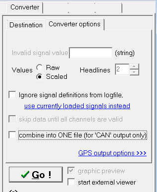
Additional (less frequently used) settings for the CAN logfile converter
can be defined on the tabsheet "Converter" ... "Converter Options" :
-
Invalid Signal Value
-
Some analysis tools need a certain value for "invalid signals". An invalid
signal is, for example, a signal which has not been received yet. The value
from this edit field will be copied into the output file as long as a signal
is invalid. Once a signal has been received, it is and remains valid.
If the output file format is a text file, you may enter any string here.
For all other file formats, this field has either no function (because the
invalid signal value is fixed), or must be a numeric value like
"-99999999".
-
Signal Values: Raw or Scaled ?
-
Has been used during development. Should be set to "Scaled" usually.
Raw: Do not convert the raw CAN value into the physical value
(do not apply offset and factor)
Scaled: Convert the raw CAN values into physical values, using
the signal's conversion parameters offset and factor
-
Headlines
-
Defines, if and how many header lines shall be written
before the actual data ("values"). Only available when converting into TEXT
files (*.txt or *.csv). The headlines contain:
- First line: Contains the column names (often: signal names) which is helpful
when post-processing the file with a spreadsheet program
- Second: If enabled, this line contains the physical units for each
data column.
- Third: Rarely used; if enabled this line contains the
logger-info-string (read from the logfile
!)
If "Headlines" is set to zero, none of these lines will be written into the
output file. For export file types like "DIAdem" and "Vector", this parameter
has no effect.
-
"Ignore signal definitions
from logfile, use currently loaded signals instead"
-
You can try to use this option to convert logfiles into signals, if the logfile
itself does not contain any (or not the right) signal definitions ... for
example, because you have only set the option
"Record all identifiers" in
the CAN logger configuration, without selecting any CAN signals from a CANdb
file (*). Be very careful with this option, and make sure you picked the
right CANdb file, which matches the CAN messages in the recording. Otherwise
you may end up with an empty (at best) output file, or an output file containing
only 'garbage'.
(*) The reason for missing CAN signal definitions in the logged file
(*.cld) may be a mistake of the person who prepared the CAN logger configuration
(logger.clc), but this may also be done deliberately by "someone" to
keep the CAN signal definitions secret. Whether a CAN logger configuration
(or a CAN logfile) contains signal definitions or not can be easily checked
with a text editor: If the file header only contains two "dummy definitions"
like the the following ...
Msg00: id=0xFFFFFFFF,mn="",nn="",wi=0

    Sig00:
    id=0xFFFFFFFF,sn="",ty=S,un="",fa=1,of=0,mi=0,ma=0,sb=0,nb=0,bo=M
.... then the logfile cannot be converted into signals (only into
a CAN message dump) without the option "Ignore signal definitions from the
logfile" - and of course, only if you have access to the CANdb files ! Details
about the file formats can be found in the appendix.
When using this option, proceed as follows:
-
before starting the converter, load the CANdb files which match
the recorded CAN-messages.
-
On the tabsheet "CANdb", select those signals which shall be written into
the output file - the same way as creating a new CAN logger configuration
(in fact, the signal definitions will temporarily overwrite definitions loaded
from LOGGER.CLC).
Only the N signals listed in the right part of the CANdb
tab will be converted (" N logged signals in x messages
").
-
After that, switch back to the tabsheet "Converter".
-
Make sure the Converter Option "Ignore Signal Definitions in
Logfile" is set.
-
Select all CAN logfiles (*.cld) which are compatible with the signal definitions
loaded above.
Remember the file selector trick to select multiple files at once (shift-
or control key pressed during mouse click)...
-
Start the conversion .
You can avoid this complexity by always adding all required CAN signal
definitions to the CAN logger configuration. The CAN logger itself will copy
these definitions to the logfile then, so the converter "automatically" knows
how to decode the signals. But in some conditions, or to keep the signal
definitions 'secret', you can use this converter option (along with the logger
option "record ALL identifiers"). Neither the logger configuration file,
nor the logfile need to contain any information about how to decode the recorded
signals then.
- Skip data until all channels are valid
- Use this option if your post-processing software cannot handle 'invalid' values.
When set, the converter will ignore everything in the original recording until all channels are valid.
The reason for a channel being invalid may be manyfold:
- A signal may be transferred very infrequently (low sampling rate),
so after starting the logger, it may take several hundred milliseconds
until all relevant CAN messages have arrived;
- A sensor may be defective, and not deliver data at all;
- Misconfiguration of the logger, e.g. wrong CAN message identifiers.
By default, this option is off which means the converter starts emitting data
immediately, even if "something" is missing at the begin. For text files, missing (invalid) data are replaced by
the 'invalid signal value' as explained further above.
- Combine output into ONE file
- This option can be used to combine multiple input files
(e.g. canlg000.cld, canlg001.cld, canlg002.cld ) into one
common output file (e.g. canlg000.asc in Vector ASCII format).
Note: At the time of this writing (2014-01-22), this option only worked
when converting CAN logfiles into the Vector ASCII format (*.ASC) !
back to top
The CAN logger can optionally record position data (from a GPS receiver)
too. To make use of this GPS-logging facility, you must convert the GPS data
into a format which your post-processing software can handle. The GPS data
can ...
-
be converted into a separate file which can be read into a mapping program
-
written into the output file which also contains the CAN signals (using extra
"data columns" for the GPS data).
Note: This is not possible with DIAdem !
-
Note:
-
You must set the option "Log Data from GPS
Receiver" in the logger configuration, before starting the CAN logger.
This option is disabled by default, because it may cost a lot of disk space.
Furthermore, you must tell the terminal which kind of GPS receiver is connected,
and how it shall be initialized. More on this can be found
here.
While converting data from a logfile which contains GPS data, the GPS track
can be plotted as a preview in a simple map window.
Unfortunately, there is are thousands of different GPS file formats, since
every GPS map software seems to implement their own track format. The CAN
logfile converter only supports the following output formats:
-
NMEA sentences saved in a text file ($GPRMC, $GPGGA only)
-
and another user-defined ASCII format
Fortunately there is a freeware tool called GPSBabel with can convert the
NMEA format into zillions of other formats - most likely, also the format
which can be imported into "your" mapping software.
A few GPS converter options are built inside the CAN logfile conversion utility.
Select the GPS tab to define your required output format:
(screenshot GPS Converter Output Options)
The GPS Converter Output Options are:
-
if logfile contains GPS data, convert the track into a separate file
(which means you will have at least two files in the destination folder:
One for the CAN signals, and another for the GPS track)
-
Track file format
defines the format of the 'separate track file' mentioned above. At the moment,
only export as NMEA strings is supported (one NMEA sentence per text line,
only $GPRMC and $GPGGA are used here).
-
Preview
opens a simple map window on which you can see
a crude image of the GPS track. Please note that this was never intended
to be a replacement for a real mapping software !
-
Place GPS data in extra columns of the main output file
PLEASE NOTE THAT THIS OPTION DOES NOT WORK PROPERLY YET ! (and doesn't work
with all destination file formats; especially writing the latitude, longitude
into 16- or 32-bit integer values makes no sense)
The table in the lower part of the GPS tab can be used to define which
GPS-columns shall be added to the output file. You don't have to fill out
this table yourself ! Instead, recall one of the "Presets" from the combo
list below the table. Only for very special applications, you may have to
edit the contents of the definition table manually. You can change the equence
of the table entries by holding the mouse down in the "Nr"-column, while
moving the cell up or down. To delete unneccessary entries, just delete the
"Title" cell. A list of possible entries in the "Contents" column is
here .
Don't forget to click the "Apply" button when the modified table is complete
(  ) .
) .
back to top
While converting your log data (which may take a fair amount of time), you
may show the converted data in graphic form. This shall not -and never will
be- a replacement for a post-processing tool, but it can give you a short
impression if "it worked". In fact, the author implemented the graphic preview
window exclusively for testing purposes, because he had no suitable
post-processing tool. Beware: the graphic preview window may still have a
couple of bugs, so if you don't really need it, don't use it... and don't
complain about the ugly colours ;-)
(screenshot Logfile Conversion Preview)
To use the graphic preview window, set the checkmark graphic
preview on the File Converter tab before clicking "Go !" to start
the conversion. The converted data will then be displayed as simple graphs
on a common screen in the preview window. Old data may be scrolled out on
the left edge of the window, when new data are added to the right.
If the display is too confusing because too many channels are visible and
overlap each other, you can turn channels of by clicking at the channel names
in the color legend field.
Note: The graphic preview only works if the file
converter's output type is set
to 'SIGNALS'. It cannot display CAN MESSAGES !
Supported DIAdem - formats
NI DIAdem® supports a large variety of file formats. The CAN logfile
converter described in this document can only generate a subset of these
formats, which are listed below.
-
ASCII
(American Standard Code for Information Interchange) - a bit outdated to
call this "ASCII", in fact all values are saved as plain text, some characters
in it may evenuse the ANSI character set.
Disadvantage: File size (usually larger than "INT32", see below). Loads a
bit slower into DIAdem than INT32.
Advantage: Files can be checked with a simple text editor. Almost unlimited
measuring time, because there is no risk of an integer overflow.
-
INT32
Saves all values as 32-bit-integer values. This is the preferred format (compared
to "ASCII"). Four bytes per number are required in the file, regardless of
the value (in contrast to ASCII, where the file size depends on the
values).
Because the 'self-written' DIAdem file converter always uses a single data
format for all written columns (to deal with a single data file
only), there are some limitations for the time channels:
- time format "absolute / YY-MM-DD hh:mm:ss": Resolution = 0.1 seconds, so
the max recording time for INT32 is (2^31*0.1sec)/(60*60*24) = 2485 days.
- time format "Seconds": Resolution = 10 milliseconds, max. recording time
for INT32 is (2^31*0.01sec)/(60*60*24) = 248 days
- time format "Milliseconds": Resolution = 0.1 milliseconds, max. recording
time for INT32 is (2^31*0.0001sec)/(60*60*24) = 2.48 days
-
REAL64
Saves all values in a 64-bit floating point format. Should be used if CAN
bus signals use floating point format ("Float" or "Double") to avoid rounding
errors. Also solves some of the problems with the time channel.
Known Issues
When testing the conversion routines into the DIAdem format, only a quite
old version of DIAdem (V7) was available for us. With this old version, there
were a lot of unexplainable system crashes, whenever trying to produce a
graphic view (with DIAdem VIEW). The sympton was a frozen mouse cursor (alias
DIAdem's steaming coffee cup), not even the final rescue grip CONTROL-ALT-DELETE
was possible then ! So we can only advise you to use extra care, make backup
copies of all important files, and be prepared for the big bang when working
with converted logfiles in an old DIAdem version.
The ASCII format of our old DIAdem (V7) obviously has meager resolution of
just ONE SECOND (because only placeholders for year, month, date, hour, minute
and second are mentioned in the specification, but no fractional values).
This is unacceptable for many applications. To circumvent this, set the format
of the time column to 'IMPLICIT' before conversion.
In this case, the utility can place a scaling factor matching the write interval
AS A FLOATING POINT VALUE in the DIAdem channel header.
Exporting GPS-Data into any DIAdem-format is impossible, because neither
the required informations nor a suitable test environment were available
at the time of this writing.
back to top
In the old 'MKT-View Plus', the logger was restricted to...
-
a maximum of 48 different logged signals (or messages) as the total number
from both CAN buses.
This limit is dictated by the time the CPU may spent in the CAN interrupt
handler for message ID filtering via software.
-
a maximum of 8 "other expressions" which may be logged.
-
a maximum peak message rate of 10000 messages per second (sum from
both CAN buses) for a very short time (a few milliseconds). Simultaneous
high traffic on both buses will cause occasional loss of single messages.
-
MKT-View I : a maximum average message rate of 1500 messages per second.
With certain cards, only 600 messages per second. Slightly more if no trigger
conditions have to be evaluated.
Higher message rates can be tolerated for fractions of a second as far as
the internal RAM buffer allows.
-
a maximum logging capacity of roughly 30 million messages on a 512 MByte
memory card.
Since the MKT-View "Plus" / MKT-View I has been phased out years ago, and replaced
by MKT-View II / III / IV by almost every customer, the above restrictions
don't apply anymore. The logger's main bottleneck isn't the CPU speed but the SD memory card.
Conflicting logger options:
-
The option Limited message
recording rate
cannot
be used together with the option
Receive and log ALL CAN message
identifiers. The reason is, every message has its own timer to
check if it must be recorded after a new reception. This can and will never
work if "ALL" message identifiers shall be written, because we would need
up to 2^11 or even 2^29 timers then. In the latter case, all messages which
are not registered in the list of logged identifiers will be written to the
logfile whenever they are received !
(Tech background: Scanning the message buffer to find out when a certain
ID was previously received doesn't work, because it would be too slow).
back to top
If CAN-Logger or CAN-Snooper have not already been unlocked by the
manufacturer (for example because you didn't order these software functions
when buying the hardware), enter the unlock-codes yourself in the terminal's
system menu. The manufacturer (MKT Systemtechnik) will provide these codes
via phone or email. Please note: The unlock-codes are tied to a device's
serial number ! The serial number is displayed in the terminal's system
menü. To enter the unlock codes, proceed as follows (here as an example
for the MKT-View "plus" with software art11089.hex) :
-
User: Invoke the system menu by pressing F2 and F3 on the terminal simultaneously
-
User: Select menu item "System Setup / UNLOCK" with cursor keys and ENTER
(alias rotary button).
(if the main system menü only has "System Setup" but not "System Setup
/ UNLOCK", there are no unlockable special functions - possibly wrong firmware)
-
User: Write down the serial number(s) from the terminal's system menu (item
"SerialNumber=XXXXX"), then contact MKT Systemtechnik (phone or email), tell
us the serial number(s), and ask for the unlock code(s) .
-
MKT: Check if the user/customer is authorized ("has paid for") the special
function(s); if yes, tell him the unlock code via phone or email.
-
User: Select "Enter UNLOCK Code" in the terminal's system menu
(press ENTER once, so the cursor jumps to the first digit of the edit field)
-
User: Enter unlock code in the system menu
(for MKT-View: use the rotaty button to increment/decrement digits, use F1
and F2 to move cursor left or right as replacement for "real" cursor keys)
-
Finish the input with ENTER and wait ...
(the terminal's firmware checks the code and shows which functions were unlocked,
like :
CAN-Logger = 1
CAN-Snooper = 1 if both functions were unlocked)
-
If required, enter the second unlock code (for example CAN-snooper, repeat
steps 5 to 7).
If and which special functions have been unlocked on a
particular device will also be displayed when entering the system menu (as
long as the keys to activate the system menu are held down).
Tips for program operation
Note: If the CAN Logger Utility was installed with an installation script,
the script will -most likely- have registered the file extenstions *.CLC
and *.CLD already. Only if the extensions were already associated with another
program, you may have to change the association yourself.
As mentioned in the chapter Starting the CAN
Logger Utility, it is helpful to associate the extensions CLC (CAN Logger
Configuration) and CLD (CAN Log Data) with the CAN Logger Utiliy.
This can be done easily with the function "Register files and extensions"
in the program's main menu:
Select "File"..."Register files and extensions". The program will ask you
which file extensions shall be associated with the CAN Logger Utility, and
-if you agree- will save these settings in the windows registry (under
"HKEY_CURRENT_USER".."Software".."MKT Systemtechnik").
When launching the program, a few parameters can be passed in the (DOS-)command
line. This is used -for example- in the Terminal Programming Tool which may
invoke the CAN Logger Utility to pass the names of the currently used CANdb
files, or to instruct the utility to load a certain file upon startup.
The command file arguments are:
-
/bm
-
Let the program run in batch mode. Without this
switch, the program runs in "interactive mode".
-
/cwNNNN
-
Programm start with client communication. The parameter NNNN is the window
handle of the client. This is required for communication between client and
server (the server sends a message to the client as soon as he is ready for
business).
-
<filename.clc>
-
Command to load a CAN Logger Configuration file (detected by the file
extension).
-
<filename.cld>
-
Command to load a CAN Logger Data file (detected by the file extension).
-
<filename.dbc>,<BusNr>
-
Command to load a CANdb filei. The <BusNr> parameter defines for which
bus the file shall be loaded (1 or 2).
-
<filename.cmd>
-
Command file mode. May replace the DOS command line if there is not enough
space in it. Every line in the command file will be treated the same way
as a single command line argument.
You may invoke the logfile converter from your own application, using the
"batch mode" switch ( /bm ) in the command line. In this mode, the program
will run "automatically", without user interaction. This means:
-
The program will not open any message box, and will never ask the user for
a decision (no "Yes"/"No"/"Cancel" - messages etc).
-
The program will automatically load the required source files.
-
The program will automatically to convert the logfiles into the desired format.
-
The program will terminate itself automatically, after the job is "done".
When using the batch mode, you should also specify one or more logfile name(s)
in the command line, and -if required- the name of the target file(s). The
utility will know which of the files are "input" and which are "output" by
looking at the extensions. Example:
CanLoggerUtility.exe /bm canlg001.cld testdrive1.dat
<work in progress>
Format of 'primary' CAN log files on the memory card
A CAN log file contains everything which you need to decode all all logged
signals. For this reason, the header contains a small database with signal
definitions in a "textual" form. The CAN logger actually writes messages
(not signals) to the memory card. A single data record in the logfile consists
of 16 bytes of information, including..
-
a flag if the entry is a CAN-message, a header, or 'other data'
-
bus number,
-
standard/extended flag,
-
11- or 29-bit CAN-ID,
-
timestamp (relative to the last absolute timestamp !)
-
count of data bytes actually received,
-
and the 8 message data bytes itself.
A complete and up-to-date desciption of the CAN logger's primary file format
may be found in this document, or obtained from
MKT Systemtechnik. Please ask the software
development engineer Mr Buescher for the "CAN-logger file format specification"
( ).
).
Format of CAN log files exported "as text"
These files are not produced by the logger itself, but with the CAN-Logger
File Conversion Utility. The utility can read the primary logfiles (produced
by the logger) and convert them to other file formats, either message- or
signal-based.
By the time of this writing (2003-10-09), the "message"-based text exported
format looked as follows. It is a human readable format which you
can analyze with a simple text editor :
Time_second CanIdentif d0 d1 d2 d3 d4 d5 d6 d7

000117.8600 0x00000123 15 00 00 00 15 00 15 00

000117.8603 0x00000301 0F 02 5F 01 03 00 03 00

000117.8606 0x32345678 02 00 02 00 03 00 03 00
Beware: The output formats are subject to change without further notice.
This especially applies to the textual display of "other" entries in the
logfile, like evaluated expressions, trigger status lines, etc.
The first column is the timestamp (here in seconds), the second is the CAN
identifier which contains the bus number and the 29-bit-flag, followed
by the message data bytes in hexadecimal form. There is no "data length code"
because CAN messages can only have up to 8 message data bytes, which you
can count yourself !
Storage medium for the old 'MKT-View Plus' (with CompactFlash memory card)
The configuration and data files are stored on a Compact Flash™ memory
card for the terminal's memory card slot. We tested a few of those cards
from various manufacturers, with sizes between 4 and 512 MByte. Be careful,
because:
For the old MKT-View "Plus", the CF memory card must be DOS-formatted !
Other formats like FAT32, NTFS, etc will not work ! Fortunately most cards
are still DOS-formatted with a 12- or 16-bit FAT by their manufacturer. If
your PC has no suitable interface for the memory card: There is a large number
of cheap interfaces for the USB port; a web search for
or
will take you further. The author used an "USB 6-in-1 Card Reader/Writer".
By the way, the CAN logfiles are usually much too large to be transferred
through the terminal's serial interface. So you *must* have some kind of
memory card interface to transfer the files !
Storage medium for 'MKT-View II' and 'MKT-View III' (with SD memory card)
These newer devices with 32-bit CPU (ARM) use an SD memory card, which must be treated
even more carefully than the old (large) CF memory card.
MKT-View II, III, and possibly all later devices support FAT16 and FAT32,
thus they are suited for disk volumes larger than 2 GByte.
- Note
- MKT-View II / III still do not support NTFS, and long filenames,
to avoid hassle with several software patents.
General notes about storage media (CF, SD)
The memory cards must be handled with care. Though some precautions were
made when constructing the terminal hardware, you should disconnect the terminal
from before inserting or removing the memory card to avoid electrostatic
discharges. During logging, some files may be opened on the memory card.
If there is a sudden loss of power during file writes, the data on the card
will be corrupted, and -worst case- the file allocation table and directory
structures will be damaged. In the latter case, use your PC and a 'Scandisk'
utility to repair the file system.
To avoid corrupted data caused by sudden power failure, the terminal (when
equipped with a memory card slot) requires two separate power lines: A switched
supply voltage, and a permanent supply. More about the terminal's power supply
can be found in the hardware manual - the description of the terminal's
power supply would go beyond the scope of this document.
back to top
As mentioned in the chapter 'Storage Media',
the terminal must power itself down in a controlled manner to avoid data
loss on the memory card. There is
-
a switched power supply line which is used to turn the terminal on
and to initiate shut down
-
a permanent power supply line from which the power for the shutdown
process is taken.
Both supply lines have the same electrical characteristics (specified in
the hardware manual). Typical supply voltages are 9.0 V .... 24 V.
If the 'permanent' suppy voltage is missing or below 9 V, the terminal will
show a warning message like
Bad standby supply voltage !

Measured: 06.8 Volt |
In this case, you should check the electric wiring, connectors, and -possibly-
the battery voltage.
DO NOT CONNECT BOTH SUPPLY VOLTAGES IN PARALLEL ! Data losses and a corrupted
file system on the memory card will be the result, when the 'permanent' voltage
is turned off together with 'switched' voltage, so the terminal has no chance
to close all opened files properly.
Because there may be the risk that both supply voltages may drop below 9
Volts when starting the engine of a passenger car, the terminal must be informed
if the power is "reliable" or not. More details are in the chapter about
the power-good-flag.
If there is something wrong with your supply voltages or the cable connections,
you will get this message when turning the terminal's power on :
SOS - Device has not been shut down

	properly,maybe the supply voltages

	are connected in parallel ?


	! RISK OF DESTROYING THE MEMORY CARD !

	! NOW USE MS-"SCANDISK" TO REPAIR IT !
[press any key to continue] |
In this case, you should
-
Turn the terminal off, this time with a properly connected standby supply
voltage. (If you press a key to continue without turning off, the logger
will not work because write-access to the memory card is inhibited)
-
AFTER turning the power off, remove the memory card from the card slot, and
let Microsoft "Scandisk" (or a similar program) try to rescue the data on
your memory card. The terminal itself has no such utility - and never will
!
-
Examine reason for the improper shutdown. Most likely, you have connected
permanent and switched voltage in parallel, which is illegal. Use a voltmeter
(or -even better- an oscilloscope) to measure the permanent voltage in the
moment you turn the "switched" supply voltage off. In most cases the terminal
will be turned on and off with vehicle's ignition switch (DL: Zündschloss).
Make sure the permanent supply is not turned off with the ignition switch.
In a passenger car, the cigarette lighter is sometimes "switched", sometimes
not ! More information about the terminal's power requirements can be found
in the hardware description.
-
Make sure the interpreter command power=1 is
not executed too early in your application !
-
Turn the terminal on again. If the last shutdown was ok, the "SOS"-message
shown above will not appear again.
Notes:
-
Power from the "permanent" (or "standby") supply is only drawn for a couple
of seconds..
-
In fact, the "permanent" supply voltage only needs to last for a few seconds
to shut the terminal down properly. The time depends on the amount of data
which must be "flushed" to the memory card before turning off. Pessimistically
we specify "at least five seconds" though the shutdown process is usually
much faster.
-
When the shutdown process is finished, there will be a black 'curtain' rushing
across the LC display. If you see this curtain, you know the terminal has
finished the shutdown sequence ... just like an ancient PC saying "It is
Now Safe to Turn Off Your Computer" ("Sie können den Computer jetzt
ausschalten"). If the terminal does not turn itself off after this, there
may have been a too short gap in the switched supply voltage (because the
terminal cannot turn itself off as long as the switched voltage is connected
!). You will see a message like this :
-
Error: Shutdown-Relais does not work !

Fehler: Abschalt-Relais tut's nicht ! |
-
The terminal's real-time clock is powered from a little battery inside the
terminal. It is not affected by the external supply voltage.
-
Problems caused by collapsing power supply voltage can be eliminated with
the optional "Powerbox" (planned for spring 2006 - please ask the manufacturer
for details).
back to top
Namings for products in this manual, that are registered trademarks, are
not separately marked. The same applies to copyrighted material. Therefore
the missing ®(r) or ©(c) does not
implicate, that the naming is a free trade name. Furthermore the used names
do not indicate patent rights or anything similar.
CANdb®, CANoe, CANalyzer are trademarks or registered
trademarks of Vector Informatik GmbH.
Compact Flash™ is a trademark of Sandisk Corp.
Intel® and the Intel logo are registered trademarks of Intel
Corporation.
NI DIAdem is a registered trademark of National Instruments
Corporation.
Excel, Microsoft, Windows, Win95, WinNT, WinXP® are registered trademarks
of Microsoft Corporation.
THIS SOFTWARE IS PROVIDED BY MKT SYSTEMTECHNIK ''AS IS'' AND ANY EXPRESS
OR IMPLIED WARRANTIES, INCLUDING, BUT NOT LIMITED TO, THE IMPLIED WARRANTIES
OF MERCHANTABILITY, FITNESS FOR A PARTICULAR PURPOSE, OR NON-INFRINGEMENT,
ARE DISCLAIMED. IN NO EVENT SHALL THE AUTHORS OR THE DISTRIBUTOR BE LIABLE
FOR ANY DIRECT, INDIRECT, INCIDENTAL, SPECIAL, EXEMPLARY, OR CONSEQUENTIAL
DAMAGES (INCLUDING, BUT NOT LIMITED TO, PROCUREMENT OF SUBSTITUTE GOODS OR
SERVICES; LOSS OF USE, DATA, OR PROFITS; OR BUSINESS INTERRUPTION) HOWEVER
CAUSED AND ON ANY THEORY OF LIABILITY, WHETHER IN CONTRACT, STRICT LIABILITY,
OR TORT (INCLUDING NEGLIGENCE OR OTHERWISE) ARISING IN ANY WAY OUT OF THE
USE OF THIS SOFTWARE, EVEN IF ADVISED OF THE POSSIBILITY OF SUCH DAMAGE.
FURTHERMORE THE AUTHOR IS NOT LIABLE FOR VIRUSES AND OTHER FORMS OF "MALICIOUS"
SOFTWARE WHICH MAY HAVE INFECTED THIS SOFTWARE, AND ANY DAMAGE OF ANY KIND
RESULTING FROM THIS.
HIGH RISK ACTIVITIES
The Software is not fault-tolerant and is not designed, manufactured or intended
for use or resale as on-line control equipment in hazardous environments
requiring fail- safe performance, such as in the operation of nuclear facilities,
aircraft navigation or communication systems, air traffic control, direct
life support machines, or weapons systems, in which the failure of the Software
could lead directly to death, personal injury, or severe physical or
environmental damage ("High Risk Activities").
MKT Systemtechnik specifically disclaim any express or implied warranty of
fitness for High Risk Activities.
Latest modifications (with date in ISO8601 format, YYYY-MM-DD)
2014-02-04: Added the option to log script variables.
2011-02-17: Implemented and documented support for the ETAS ASCII format (*.ascii, "ETASAsciiItemFile")
back to top