
Importing signal definitions from AUTOSAR XML files
![]()
![]() (caution: only available for certain terminals, not for CANopen)
(caution: only available for certain terminals, not for CANopen)
Overview
See also:
- Manual for the programming tool (not CAN-specific)
- Frequently Asked Questions
- The Feature Matrix, with a list of devices that support CAN / CAN FD ("without CANopen")
Introduction
In this document, the term "AUTOSAR" refers to "AUTomotive Open System ARchitecture";
"CANdb" refers to CANdb Network Files.
Before the introduction of AUTOSAR, CAN database files (with the extension DBC)
were widely used to store all information about a CAN network (not CANopen).
The DBC file format, introduced by Vector Informatik, was a de-facto standard
in the automotive industry (mainly for passenger vehicles).
In 2020, MKT Systemtechnik made their first attempt to import CAN signal
definitions from AUTOSAR XML files. In contrast to *.DBC ('DataBase for CAN'),
AUTOSAR XML (files with extension *.ARXML) does not only support CAN, but many other
bus systems. Despite being XML, the structure of ARXML files can be incredibly complex,
and there are a huge number of different versions / flavours of AUTOSAR XML.
In fact, there is no single/simple 'AUTOSAR XML file specification', but there are
'AUTOSAR XML Schema Production Rules' which specify how a manufacturer's
AUTOSAR meta-model can be compiled into an XML schema to describe
the actual structure of the AUTOSAR XML file.
Thus, AUTOSAR XML is more difficult to parse than "CANdb" (*.DBC).
Potential customers interested in the AUTOSAR import (especially welcome: users of AUTOSAR Version >= 4.3.0)
please get in touch with us (MKT Systemtechnik).
At the time of this writing in autumn 2020, we didn't have anything to test
dynamic, multiplexed PDUs (neither ARXML files nor a CAN / CAN-FD network with such PDUs).
As a 'thank-you' for cooperation, you will receive updates directly from the developer
with improved support for your AUTOSAR version.
Many thanks for your cooperation in advance !
The programming tool can only read a small subset of the objects which may
be contained in an AUTOSAR XML file. The tool's built-in XML parser isn't aware
of XML schema files (instead, it looks for hard-coded keywords in the XML),
so if the AUTOSAR import doesn't work with a certain file, use an ARXML-to-DBC
file converter instead, and import the converted DBC. This should work as long
as the CAN signals you want to display or log are not in a 'Container PDU' or
similar concept that cannot be described in a DBC file ('Database for CAN').
AUTOSAR-import features supported by the programming tool in 2020-07 :
- Data signals with 1..32 bit, travelling over the CAN-Bus as SIGNED or UNSIGNED INTEGER VALUES
- Data signals with 32 or 64 bit, travelling over the CAN-Bus as FLOATING POINT values
- Multiplexors and multiplexed signals (once called "mode signals" and "mode-dependent signals")
- Motorola or Intel byte order
- Conversion factors and offsets from the raw "signal" value into a floating point number for the display
The "CAN display terminal" alias "MKT-View" is a special variant of MKT's
UPT (User Programmable Terminal), which only uses 'Variables' internally.
Some of these variables may be connected to 'Signals',
while other variables may be connected to the outside world via CAN, CAN FD,
or Ethernet. Other variables may be unconnected, to use them only 'locally'
for temporary storage inside the terminal application.
Importing AUTOSAR XML file into the programming tool
To use signal definitions from a CAN DBC or ARXML file, switch to the tool's CAN tab.
With the buttons Load DBC #1 and Load DBC #2
buttons, import some signal definitions. To import AUTOSAR (ARXML) instead of DBC files,
change the file selector dialog's "File Type" ("Dateityp") from
DataBase for CAN (*.dbc)
to
AUTOSAR XML(*.arxml),
and select the file to import.
Alternatively, you can import multiple AUTOSAR XML files at once (if they are
located in the same folder) as described below:
In the programming tool's main menu, select 'Tools' - 'AUTOSAR Import'.
A 'Browse-for-Folder' dialog (in German: 'Ordner suchen') pops up,
preset with the 'AUTOSAR' folder from the tool's Settings tab.
After selecting the folder with our AUTOSAR XML files, click 'OK'.
If the AUTOSAR version is sufficiently compatible, the programming tool will now extract
all it needs to know about signals travelling on CAN / CAN-FD buses (including their PDUs),
and display them in a tree view, from where individual signals can be selected
for later processing (converted into 'signal definitions' that the MKT-View can handle).
2.1 Browsing an imported AUTOSAR file in the 'Tree View'
Per default, the 'Tree View' displayed on the 'CAN' tab (for historic reasons) shows the data imported from the AUTOSAR XML file(s) in a similar structure as in the file itself (*.arxml).
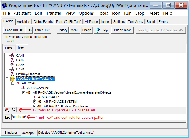
Programming tool with tabsheet 'CAN' after importing AUTOSAR XML.
Note the nesting of 'AR-PACKAGES' in this particular case.
To manually navigate through the tree, nodes marked with [+] can be expanded (along with their children, grandchildren, etc). Nodes markes with [-] can be collapsed (again, along with their children, etc) to hide information that you don't need.
The buttons below the 'Tree View' can be used to expand the entire Tree View (all nodes in all imported files, which may take some time), collapse the entire tree, and to find text (with wildcards like '*' and '?') in all nodes of the tree.
2.1.1 Searching items in the Tree View
As already noted in the introduction, AUTOSAR XML files (and thus the default tree view) can be incredibly complex, deeply nested, and contain an lot of information not related to the network ("bus") that the MKT-View will be connected to.So the 'challenge' will be how, and where to find the relevant signals for your application.
Let's assume you have a vague idea about the names of signals that you want to display (with the MKT-View), but you don't know the exact spelling, and you don't even know which of the imported files (and thus which root of the Tree View) contains it.
For example, your initial guess is the signal name contains the string 'light' because your application has to deal with headlights, rear lights, or interior lights. There may be leading text before, and trailing text after the 'light', so you use two wildcards (placeholder '*' representing any character) in the search pattern:
*light*After entering this in the edit field for the search pattern, hit the ENTER key, or click on the 'Find text' button near the edit field.
Beginning at the currently selected node (or the top of the Tree View, if nothing was selected), the programming tool will recursively search the tree for the next occurrence of the search pattern. The following characters have a special meaning in the search pattern:
* : Placeholder for 'any string' (with any length)? : Placeholder for a single characterIf the search pattern matches a string of characters in any of the tree nodes, the programming tool will automatically expand the tree (to make it visible), and select / highlight it with a blue background. Additionally, a text field above the tree view will list a few details about the node where the text was found, e.g.:
Found '*light*' in AUTOSAR node 'VALUE-REF: DEST=ECUC-CONTAINER-VALUE val=/ActiveEcuC/Com/ComConfig/sig_State_RearInteriorLight'
If you think you found the right one for your application, drag and drop the signal definition into the list of display variables right next to the tree view. Details about that (and which kinds of AUTOSAR elements can be dragged) in the next chapter.
Below are a few examples for search patterns, as currently supported by the programming tool:
- FIBEX*
- Searches for anything (node name, value, attributes, or automatically generated node descriptions)
beginning with the string 'FIBEX' .
Since there are upper-case characters in the search string, the search will be case-sensitive.
- *error
- Searches for anything ending with the string 'error'.
Since there are no upper-case characters in this search string, the programming tool assumes you want a case-independent search, thus matching results may include strings like 'UnderVoltageError'.
- CAN-FRAME-TRIGGERING
- Searches for a perfect match (without wildcards) in all node names, node values, node attributes.
Since CAN-FRAME-TRIGGERING has a special meaning in AUTOSAR XML, there will most likely be hundreds of matches for this string in your database.
Note: To find details about 'CAN-FRAME-TRIGGERING' in the AUTOSAR specfification, search for 'CanFrameTriggering' (camel-cased), because there is no simple one-to-one relation between XML node names in the *.arxml file and in the AUTOSAR 'Meta-Model Element'.
- CAN-FRAME-TRIGGERING:NewFrame*
- Searches for a match (with wildcards) for all 'CAN-FRAME-TRIGGERINGS' with a (short) name
beginning with 'NewFrame', because in this tool, the colon separates an XML node name
and the nodes 'short name' (extracted from a child named 'SHORT-NAME' in the XML file).
- *-REFS
- Should find lots of 'references' (in German: Verweise) in the imported AUTOSAR file(s).
Examples:
- ARXMLContainerTest.arxml:/VectorAutosarExplorerGeneratedObjects/Frame/Signal
- Searches for something named 'Signal' along the specified path, but only in tree nodes
imported from file ARXMLContainerTest.arxml (because the part before the
separating colon is obviously the name of a file, not an XML element).
This only works as long as the specified file is still loaded.
- Note:
- Same as a reference (element name ending with _REF) in AUTOSAR,
these paths consist of the 'short names' in AUTOSAR, not the type names.
For example, 'VectorAutosarExplorerGeneratedObjects' is such a 'SHORT-NAME' (even though not really short),
2.1.2 Selecting 'signals' for the display in the AUTOSAR Tree View
To use some signals in the terminal later, you supply a unique variable name for every used signal.For the MKT-View, a variable name must always begin with an uppercase letter to be recognized later by the display interpreter, and the length of a display variable name may be restricted !
You can either type a variable name in the left column of the table, of double-click into a line of the table to generate a variable name automatically from the CAN signal name.
After defining variable names for all signals you want to use, you can transfer them to the "Variables" sheet.
Finally, click the button Ready, transfer to Variables for this purpose.
You are now ready to use the variables in your display application just like
any other (connected to SDO, PDO, or not connected at all).
On the left side of the CAN Import Page, you can select a
single node, a message from that node, and a signal from that message. The
selected message will be highlighted in the table. Other signal
definition lines from the same message are marked with a light blue
frame, other messages from the same node are marked with a light green frame.
You can select a single signal by clicking into one line (row) of the definition table, or in the listbox Signals of message.
- Note:
- If you have hundreds of signals in different nodes and messages, first select the node, then the message, and finally the signal. This is much faster than scrolling through hundreds of lines in the definition table.
Right-clicking into any of the lists or the CAN definition table opens a popup menu which shows all options for the currently selected node, message, or signal.
The columns in the definition table are:
-
VarName
Will be explained in another chapter. -
Bus Nr
1 for the first CAN interface, 2 for the second CAN interface, etc (if supported by target hardware) - Signal Name
-
Type
Data type of the signal in 'raw' form, i.e. "as it travels on the network". This is typically a signed or unsigned integer, but it may be a 32- or 64-bit floating point number. -
Unit, Factor, Offset, Min Value, Max Value
Properties of a signal, read from the database file. -
Mapping
Will be required later to extract a signal from a message. The first parameter is the bit position of the signal's least significant bit within a CAN telegram; no matter if INTEL or MOTOROLA, the bits in the first byte are numbered from 7..0. (beware: some CAN database editors use a different numbering system).
See also: Notes about the counting of bits within a CAN- or LIN-frame at the end of this chapter. -
Attributes
Not used yet. We don't support attributes.
-
Message Definition
Will be required later in the terminal to program the CAN controller for receiving the desired CAN message. The first part of the definition is the CAN identifier, the second part is a flag if 11 or 29 bit identifier shall be used (standard or extended frames) -
Multiplexor (alias "Mode Signals" and "Mode-dependent signals")
Multiplexors are sometimes used if more signals shall be distributed via CAN than the 8-byte data field would allow, without sacrificing additional CAN message identifiers.
Depending on the multiplexor, the rest of the CAN message data field is decoded in a different way ("as if transmitted with a different ID"). -
Comment
May contain a few letters from the 'comment' field of a signal definition.
back to the chapter overview
The 'CAN Message Layout' display window
The layout of a CAN message (or, beginning with the MKT-View V, CAN FD) can be displayed in graphic form. This helps to resolve problems with the bit numbering scheme, which can be confusing if you use CAN database editors from different manufacturers (for example, some reverse the bit numbering in a CAN frame depending on the message type or endianness ("Intel" / "Motorola" byte order). We don't... we always use the same bit numbering scheme within a CAN, CAN FD or LIN-frame, also when accessing the data field in the script language ). Here is an example for a graphic display of a CAN message with various CAN signals (click on the Graphics button on the 'CAN' tab to open it) :
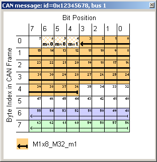
Screenshot of the graphic CAN message display.
Hatched bits show a signal's multiplexor.
Signals are marked by arrows; they point from LSB (start) to MSB (arrowhead).
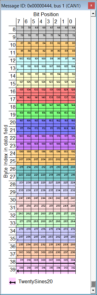
For CAN FD, the original graphic 'CAN Message Layout' display was drilled up to show up to 64 data bytes in the message payload.
The screenshot on the left shows a part of the CAN FD data field, containing 20 signals with 16 bits each (as usual, click into the image to magnify it). Despite being magnified by the operator, the window is too small to show the entire message (data field), so the programming tool automatically turned on a vertical scrollbar to control the byte offset within the message (see labels on the graphic's left edge - it shows those zero-based byte indices).
Of course the table's headline, and the legend in the lower part are not scrolled along with the table data.
A mouse click into the graphic message layout switches the currently selected signal. When selecting a different signal this way, the programming tool also switches the currently selected signal in the 'CAN' definition table of the main window.
The currently selected signal is marked by a thicker arrow in the graphic. The arrow starts at the signal's least significant bit, and ends with the arrow head at the most significant bit.
A similar display is used in Kvaser's free CAN database editor.
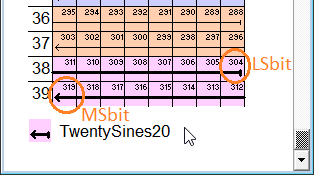
Magnified display of the currently selected signal
in the CAN / CAN FD 'Message Layout' window,
with signal name shown in the legend (bottom part),
and zero-based byte indices shown on the left side.
The numbering of bits within the entire data field uses the same (zero-based) principle as in the script language, regardless if the data field contains signals in "Motorola-Format" or not. Thus the 16-bit sample signal 'TwentySines20', spanning from bits 304 to 319(!), occupies the last 2 bytes of a hypothetical 40-byte frame.
Note
Since the introduction of 'dynamic multi-PDU-to-frame mapping' in AUTOSAR release 4.2.1, such a 'static' message layout display doesn't make sense anymore, because 'dynamic' PDUs don't occupy fixed locations with CAN/CAN-FD-frames.
Instead, anything may be variable at runtime, and at the time of this writing (2020-08), it wasn't sure if and how to cope with this severely increased complexity.
Appendix
The appendix contains some additional info, which you don't need for 'normal'
operation. You don't necessarily have to read and understand this ...
but please take a look at the legal terms !
Legal Terms, Disclaimer, etc
Namings for products in this manual, that are registered trademarks, are not separately marked. The same applies to copyrighted material. Therefore the missing ®(r) or ©(c) does not implicate, that the naming is a free trade name. Furthermore the used names do not indicate patent rights or anything similar.
The word AUTOSAR and the AUTOSAR logo are registered trademarks of the AUTOSAR Development Partnership.
The software and accompanying written materials (including instructions for use) are provided "as is" without warranty of any kind. Further, MKT Systemtechnik does not warrant, guarantee, or make any representations regarding the use, or the results of the use, of the software or written materials in terms of correctness, accuracy, reliability, currentness, or otherwise.
The entire risk as to the results and performance of the software is assumed by Licensee and not by MKT Systemtechnik or its distributors, agents or employees.
THERE ARE NO OTHER WARRANTIES, EITHER EXPRESS
OR IMPLIED, INCLUDING BUT NOT LIMITED TO
IMPLIED WARRANTIES OF MERCHANTABILITY AND FITNESS
FOR A PARTICULAR PURPOSE,
WITH RESPECT TO THE SOFTWARE, THE ACCOMPANYING
WRITTEN MATERIALS, AND ANY ACCOMPANYING HARDWARE.
MKT Systemtechnik
Hasskampstrasse 75-77
32257 Bünde (Germany)
Phone: 05223/493933-0
Fax: 05223/493933-20
Last modifications:
- 2020-07: First experiments with AUTOSAR XML. Unfortunately there were no
*.arxml sample files freely available for recent AUTOSAR versions (4.4.0 ?),
so the 'functionality' implemented in MKT's programming tool so far
is very 'basic':
- our importer doesn't care for XML schemas,
- it doesn't care for AUTOSAR template profiles, models, meta-models, etc,
- thus it cannot validate the AUTOSAR XML against an AUTOSAR XML schema
- so far, 'dynamic multi-PDU-to-frame mapping' is neither supported
by the programming tool nor by the device firmware.