CAN Display Terminal : HTTP Server Details


File: cproj/UPT_xx/http_server_info/srv_info_01.htm (in english language)
Web: http://www.mkt-sys.de/http_server_info/srv_info_01.htm
Author: Wolfgang Buescher
Date: 2018-08-15 (ISO8601)
Contents
-
Connecting the embedded web server
-
Features and built-in webpages of the terminal's built-in HTTP server
- Embedded Server 'Main' page
- Embedded Server 'Remote Control' page
- Debugging tools in the web server (Trace, Script, Variable Dump)
- The 'Device Setup' page
- The 'Network Setup' page
- DHCP, Static versus Dynamic IP addresses, Hostname
- CAN-via-UDP, FlexRay-via-UDP
- Wireshark-compatible 'Packet Capture Buffer' (optional)
- Accessing the (pseudo?-) file system via HTTP
- The root folder of the pseudo file system
- The 'Data' Flash area (files/data_flash)
- The 'Audio' Flash area (files/audio_flash)
- The 'Font' Flash area (files/font_flash)
- Files on the memory card (files/memory_card)
- Files in the RAMDISK (files/ramdisk)
- Uploading files (firmware and display application)
- Select files for uploading
- Process files after uploading
-
Special tokens in the HTML templates
-
Special filenames in the HTTP server
- Reading the framebuffer from a remote device (as a bitmap file)
- Sending mouse and keyboard events to the remote device
- Remotely invoking a command (procedure) in the display interpreter
- Remotely evaluating an expression (funcion) in the display interpreter
- Reading the optional Wireshark-compatible 'Packet Capture'-Buffer
-
Troubleshooting
- Configuring Windows 7 for a point-to-point connection via Ethernet cable
-
Links and further reading
This document contains information from a developer for developers
about controlling the terminal through a web browser.
With a few exceptions, the HTML pages of the terminal's internal web server are located in the
terminal's ROM. Thus they cannot be modified without re-compiling the firmware.
Dynamic content is generated on-the-fly, while reading a page, as explained later in this document.
The document you are reading at the moment is not located in the embedded device's HTTP server.
Most likely, one of the HTML pages in the terminal's ROM (sent to your browser
by the HTTP server) contained a link to the MKT
website, where this document (http_server_info/srv_info.htm) is stored.
For software developers, this document contains a few tricks on how to use
the terminal's HTTP server for your own purpose (for example, remotely
controlling the terminal from your own application).
More on that in a later chapter.
Let's begin with the basics.
Depending on the device's network setup, there are different ways to connect the web server from your internet browser:
- If DHCP is available and configured in the device's network setup, try this method:
- Enter the device's hostname in the browser's address bar.
For all UPTs (User Programmable Terminals, including MKT-View),
the default name is UPT .
If the browser acts stupid and 'googles' for the hostname instead of trying to connect it, enter a fully qualified URL like http://UPT .
If the browser acts overly smart and replaces the name upt by stuff like www.upt.com in the address bar,
try to stop it from doing this(*) .
Note: The name (hostname) "UPT" is only valid inside your local area network. It's not a "worldwide web address" !
- If DHCP is not available, a fixed IP address must be used:
- Enter the device's fixed IP address in the in the browser's address bar. For many UPTs (User Programmable Terminals, including MKT-View),
the default fixed IP address (only valid in your local area network) was 192.168.0.243 .
Acessing a device without DHCP via the device's hostname was often difficult under windows
- how to fix such problems is explained in a Microsoft article titled
'Cannot Connect to Remote Systems Using Host Name'
(only for advanced PC users - editing the 'hosts' file is not everyone's cup of tea,
thus the suggestion to access DHCP-less devices via numeric IP address).
- If DHCP is used (i.e. the IP address is variable), but hostname cannot be resolved into an IP address by the browser:
- Try yourself to find out the IP address which has (hopefully) been assigned to the device,
and enter it in the in the browser's address bar.
If you have (physical) access to the device, you can read the leased IP address, and the device's hostname
on the screen for a few seconds (unless this has been suppressed through the device's
configuration
).
Example:
DHCP: local IP = 192.168.0.114
      hostname = 'UPT'
|
For the example shown above, you could either type UPT (without quotes!),
or 192.168.0.114 in your browser's address bar.
- If the UPT is 'very remote' and can only be connected via internet, but not in the local network (LAN):
- Please ask your network administrator, because the device will usually be hidden behind a firewall.
To access the device from 'outside' (through the world wide web, not just in the local area network), the admin must configure
the firewall so the device has its own (unique) IP address for the 'outside world'.
Note that the IP address seen on the 'worldwide' side of your DSL router will be different from the IP address in the local network !
The display itself isn't aware of whether it is connected to the "internet" (www) or just to the local network (LAN).
If the device is configured for DHCP (and NETBIOS) in the
network setup,
try UPT (short for "user programmable terminal") instead of a numeric IP in the browser's address bar.
- (*)
To stop Firefox from automatically inserting 'www.' at the begin, and '.com' at the end of the address,
enter 'about:config' in the address bar,
and change the value of
- browser.fixup.alternate.enabled
from 'true' to false. After this, entering a hostname like 'upt' will not be replaced by stuff like 'www.upt.com',
and the browser will not switch to a website which you never intended to visit.
The UPT programming tool itself can also emulate the embedded web server, so you can test it without a real device.
To emulate the 'embedded' web server in the programming tool, you may have to allow this in the firewall (inside your PC),
before enabling the HTTP server emulation on the UPT programming tool's 'Settings' tab:
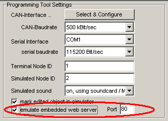
(Screenshot from the UPT programming tool, 'Settings' tab, 'Programming Tool Settings')
If the UPT programming runs on the same PC as the web browser, enter the 'local' address in the browser's address bar:
http://127.0.0.1 .
If the web server doesn't use port number 80 (=default for HTTP), include the port number in the URL. Example:
http://127.0.0.1:81 .
Due to memory restrictions, the terminal can accept one single HTTP connection
at any given time. The protocol used is HTTP/1.0, sitting on top of a simple
but small TCP/IP implementation (LwIP). Since the TCP/IP protocol stack may be used
for other purposes as well, the speed of the HTTP server greatly depends
on the amount of "other work" performed by the CPU.
The web server supports the HTTP GET and POST methods. GET is used to read
"files" (usually, HTML documents) from the server, while POST is used to
submit the contents of a form, from the client (web browser) to the server.
The next paragraphs describe a few of the HTML documents ("pages") built inside the server.
The links to the embedded server itself only work if..
- The device (display terminal) is accessable via Ethernet / LAN
- The device's host name is still set to the default value, which is UPT
- DHCP and NetBIOS-compatible hostname resolving are available in your network
- The web server is not disabled. (It may have been disabled by setting the HTTP port number to zero in the network setup,
for security reasons, prevent reading display values via web interface, prevent remote debugging, etc)
This page (upt/index.htm or just UPT by default)
shows the display's graphic screen, permanently refreshed without Javascript.
It may flicker on certain browsers. In Firefox V14.0.1, it did not flicker.
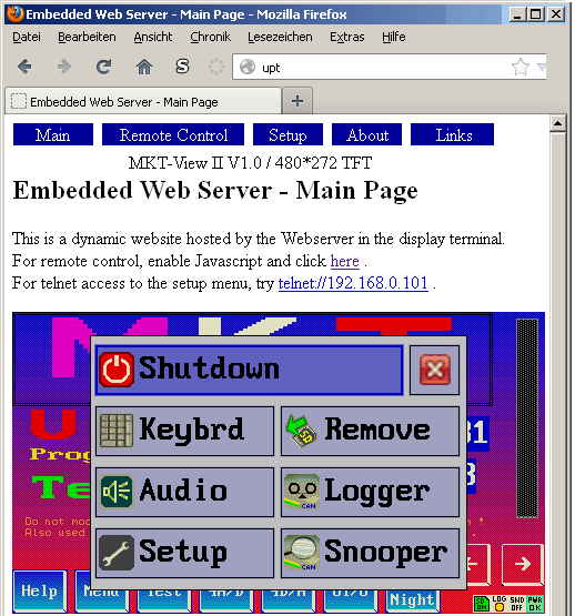
(Screenshot of the Embedded Web Server's 'main' page)
Due to the absence of Javascript on this page, remote control (using the mouse
as a replacement for the touchscreen in the 'real' device) is not possible.
This page (upt/remctrl.htm by default)
also shows the display's graphic screen, periodically refreshed via Javascript.
On most web browsers, it doesn't flicker. But it requires Javascript,
especially to trap mouse clicks into the graphic screen, and pass them on
to the remote device to emulate touchscreen events.
The main purpose of this server page is to control the device remotely.
For example, if you have a LAN connection between the device and your PC
(possibly with a wireless LAN in between), you can use your favourite web browser
to see the current display screen, or to present it to a larger audience.
You can even operate the display remotely, using the mouse (and
a piece of Javascript which runs in your browser) as a replacement for the
display's touchscreen.
To do this, first enable Javascript in your browser (if not already enabled),
then follow the link to the 'Remote Control' page.
If the device is configured for DHCP (and NETBIOS) in the
network setup,
try upt/remctrl.htm (default name; short for "user programmable terminal") .
On the 'Remote Control Test' page, you will see a bitmap (image) which is
periodically refreshed with the current content of the display (MKT-View
II, III, IV, etc).
Clicking into that image emulates a 'touchscreen event'. Graphic buttons
and the virtual keyboard can be remotely operated this way.
Keyboard input in the web browser is sent to the remote display (also using
Javascript); at least with Firefox V4 this worked sufficiently well.
To enter the terminals's system menu, you would usually press and hold the
2nd and 3rd function key on the terminal's own keyboard simultaneously.
This doesn't work in the browser. As a replacement, press the 'windows' key,
or the 'menu' key which is close to the left CONTROL key ("Strg" on a german
keyboard). On a Mac, press one of the 'Apple' keys instead (this has never
been tested, though).
At least on the default 'Remote Control' page, you will find a small panel
which can be used for software testing:
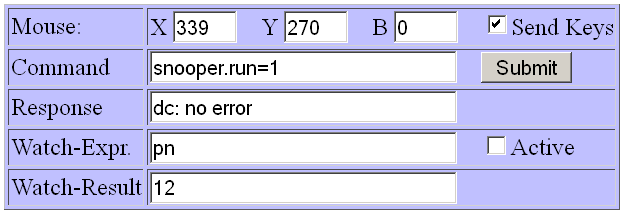
You can enter a display command in the 'Command' field, and click on the
'Submit' button to execute that command (remotely, in the MKT-View or similar
device). A few milliseconds later, a response from the terminal will be sent
back through the TCP/IP connection, and displayed in the 'Response' field.
The field labelled 'Watch-Expression' can be used like the 'watch window'
in the programming tool: You can enter a numerical expression for the display
interpreter here, which will be periodically sent to the remote display (set
the 'Active' checkmark for this purpose), and the numeric result will be
sent back a few milliseconds later. The result (=the "evaluated" expression)
is displayed in the 'Watch-Result' field. To evaluate multiple expressions
in one field, separate them with commas.
Due to the small screen of mobile devices (smartphones and similar),
when invoking the 'Remote Control'-page from such a device, only the framebuffer
and a few buttons (on the right side) are displayed:
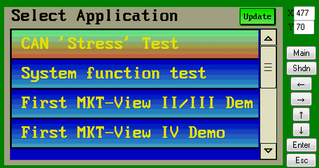
Screenshot of the 'Remote Control' page on a smartphone,
with periodically updated framebuffer on the left.
When remotely controlling the device via smartphone (as in the above screenshot), the 'Main' button switches back from
the remote control page to the web server's main page (index.htm).
Touching th 'Shdn' button opens the Shutdown window
in the remotely controlled device. Other buttons emulate the cursor keys, Enter, and Escape.
When remotely controlling the device via browser on a PC, the above buttons are left out because a piece of Javascript running in the browser
sends all keyboard events from the PC to the remote device.
Technical note: The webserver detects if the 'visitor' is a smartphone or a PC with a 'big screen'
by means of the 'User-Agent' header (string).
Browsers like Firefox or Chrome allow spoofing
any User Agent you like, which can be used to emulate a smartscreen for testing purposes.
As of 2015-03, the embedded web browser in MKT-View III / IV only checks for the following keywords
in the 'user agent' string to tell mobile devices (smartphones etc) from PCs:
"Android", "BlackBerry", "Mobile".
The embedded web server contains some tools for debugging, i.e. for development.
These are:
Note: "UPT" is just a default hostname. It may have been modified through the device's Network Setup page.
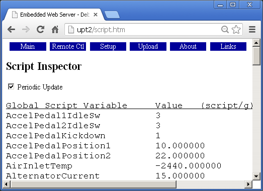
(Screenshot of the 'Script Inspector' page, displayed in a modern browser anno 2013)
The option 'Periodic Update' periodically reloads the page from the embedded web server.
Unfortunately, in certain browsers, the vertical scrolling position were reset (to the start)
whenever certain parts of the page were reloaded to update the display.
This annoying 'feature' renders the 'periodic update' option quite useless on such browsers.
In October 2013, the 'Iron' browser (a Chrome clone which claims better privacy)
appeared to be well suited for this purpose, because it did not reset
the scroller position each time the page reloaded itself.
The remote script debugger doesn't require any special software - it runs in a web browser,
using a piece of Javascript loaded from the programmable device.
No internet connection is required, because all required (java-)scripts are stored in the devices ROM.
The example below shows a script function (actually a timer event handler for periodic CAN bus transmission)
which had been stopped by hitting a breakpoint (in line 129, marked in red), after executing a single step,
so the instruction to be executed is in line 130 (marked in green).
Source-level debugger  (script/d)
   123:
   124: //--------------------------------------------------------------------
+  125: func OnCANtxTimer( tTimer ptr pMyTimer )  // a TIMER EVENT HANDLER...
+  126:   local tCANmsg msg;  // use LOCAL variables (not globals) in event handlers !
+  127:   msg.id := 0x335;    // set CAN message identifier for transmission
+  128:   msg.len:= 8;        // set CAN data length code (max. 8 bytes = 2 doublewords)
*  129:   msg.dw[0] = 0x11223344; // set four bytes in a single doubleword-move (faster than 4 bytes)
>  130:   msg.dw[1] = 0x55667788; // set the last four bytes in the 8-byte CAN data field
+  131:   can_transmit( msg ); // send the CAN message to the bus
+  132:   return TRUE; // TRUE = 'the event has been handled here' (FALSE would not fire more timer events)
○  133: endfunc; // OnCANtxTimer()
   134:
   135:
With IE (Internet Explorer), the debugger will usually not work (due to the caching of AJAX responses in IE).
Use a better browser like Firefox, Chrome, or one of the Chrome-clones with improved privacy.
The indicators on the left side of the sourcecode lines are slightly different from those used in the
UPT programming tool,
because the web-server based remote debugger doesn't use bitmaps for these indicators.
The following characters are used as indicator symbols for the remote debugger:
- Only spaces before the line number: "Not executable"
- There is no executable code in this line; thus no breakpoint can be set here.
- o : "Executable code, but not 'been here' yet"
- There is executable code in this line, but it has not been executed yet
since the debugger session was started, or the 'been-here' markers were cleared.
- + : "Been here"
- There is executable code in this line, and it has been executed at least once
since debugging started, or the 'been-here' markers have been cleared.
Note: The 'been-here' markers are not updated as long as the debugger has not been started,
because updating the 'been-here' markers (and checking for breakpoints) consumes some additional
CPU time. Thus you may not see the 'been-here' markers of your own startup code (in the script),
because the script starts running a few milliseconds after power-on.
When logging out (via web browser), the debugger session is also terminated,
and the script runs at maximum speed again.
- x : "Breakpoint which has not trapped yet"
- There is executable code in this line, and a breakpoint has been set on it,
but this line has not been executed since debugging started, or the 'been-here' markers have been cleared.
- * : "Breakpoint, been here"
- There is executable code in this line, and a breakpoint has been set on it,
and the line has been executed at least once (see description of '+' above).
- > (angle bracket pointing right) : Current program pointer
- Indicates the currently 'executed' line.
See also: Debugging with the UPT programming tool
This page (upt/setup.htm by default)
contains some basic system settings, which would otherwise be modified
in the device's own 'System Setup' menu.
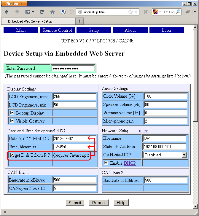
(Screenshot of webpage 'Device Setup via Embedded Web Server')
Before submitting the form, the password must be entered.
The password panel changes from blue
to green when a correct password was submitted;
red means it was wrong.
The password itself depends on the hard- and software; it may even be customer specific.
You will find it in the documentation shipped along with the hardware.
Users of MKT's Programming Tools already know the default password: It's the same as for a firmware update via RS-232.
This page (upt/nwsetup.htm by default)
can be used to change the IP related network settings (Ethernet, TCP/IP, UDP).
It can be opened through the 'more...'-Link on the small 'Network Setup' panel
on the main setup page (see previous chapter).
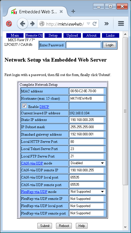
(Screenshot of webpage 'Network Setup via Embedded Web Server')
The password for the 'network setup' is the same as for the 'device setup'; see previous chapter.
The password panel changes from blue
to green when a correct password was submitted;
red means it was wrong.
- Note:
- When submitting this form, changes will be saved permanently.
Some settings require a reboot to become effective.
First fill out the password and the form, then click "Submit",
and -if necessary- finally click the "Reboot" button.
Without submitting a password, you cannot reboot the device from here.
The embedded web server can be completely disabled by setting the HTTP Server Port to zero.
If the web server has been turned off that way, you cannot turn it on through the network setup again
(because the network setup described here can only be accessed through the web server itself).
The only chance to turn the webserver on again is through the terminal's System Menu, operated locally
via touchscreen, keyboard, or rotary encoder. Details in document #85115 mentioned below.
Other network configuration parameters on this form are explained in
document #85115, "System Setup" .
The embedded device supports DHCP (Dynamic Host Configuration Protocol) as a client.
It can (and should !) be used if DHCP is available in your local network.
This saves you from a lot of hassle with conflicting IP addresses, because the DHCP server
will automatically assign an IP address to the devices, thus avoiding conflicts.
If DHCP is available, you don't need to fill out the 'Static IP address', 'IP subnet mask', and 'Standard gateway address'
in the device's network setup.
There may be a drawback with DHCP: The dynamic IP address may change with each new bootup,
so the only way to access the device easily is through its host name instead of its IP address.
The hostname itself must also be unique within the LAN, but it is much easier
to find (and keep!) a fixed hostname than finding an unused IP address which 'nobody else'
uses in the LAN.
The default hostname of all programmable CAN-bus terminals by MKT (including the 'MKT-View')
is UPT. It can be modified in the setup (basic setup or 'Complete Network Setup').
The IP protocol stack inside the User Programmable Terminal uses a
subset of NetBIOS
to resolve its hostname into an IP address. Note that due to the limited EEPROM space,
the hostname is limited to 7 characters here.
CAN-via-UDP (and, as a 'future plan', FlexRay-via-UDP) uses the User Datagram Protocol
to 'tunnel' CAN (or FlexRay) frames through an Ethernet LAN.
Details about the protocol, and its configuration, are in MKT's document
#85140, "CAN via UDP".
For a connection via CAN-via-UDP, one of the endpoints must be configured as Server, the other endpoint as Client.
Typically, an external CAN-via-UDP (or FlexRay-via-UDP) gateway acts as the Server (i.e. listens for commands on its UDP port),
while the display terminal acts as the Client (i.e. tries to connect a remote server to send or receive CAN messages through it).
The default (UDP-)port number for CAN-via-UDP, as suggested in document #85140, is 55556.
The default (UDP-)port number for FlexRay-via-UDP was unknown at the time of this writing (2013-08-07).
This feature is only available in certain devices with a special firmware (for example, MKT-View IV) !
The 'Packet Capture Buffer' stores the most recent 256 (?) kByte of packetized data, which the device
has received from, or sent to, a network (usually Ethernet, but CAN bus traffic can also be captured this way).
The buffer operates like a FIFO (first in, first out), and uses a structure compatible with 'Wireshark'
(actually, the buffer contents can be saved as a PCAPNG file). The buffer can also be inspected directly
via web server. There are also commands to start and stop the acquisition of packets in the buffer, as listed below.
- capture.htm
- Shows a part of the capture buffer directly as HTML (in your browser).
The display format tries to be similar as Wireshark - see screenshots at the end of this chapter.
- capture.txt
- Retrieves the entire buffer as a plain, 'human readable' text file.
In contrast to the HTML display, packets are not colourized depending on the protocol.
- capture.pcapng
- Reads the buffer as a Wireshark-compatible 'PCAPNG'-file ('packet capture next generation').
After filename and extension, one of the following commands can be appended to the URL (separated by space).
These commands can be used in additions to the packet capture configuration in the device's system-setup
to control the packet capture:
- /start
- Starts capturing packets (Ethernet frames and/or CAN-messages).
- /stop
- Stops capturing packets, and thus avoids the oldest data being overwritten in the FIFO (RAM).
- /clear
- Clears the entire capture buffer (FIFO in RAM).
- /time=rel
- Switch the timestamp display format to "relative; seconds since the previous packet".
After this, in the HTML-display, the timestamp column will be titled "DeltaT", i.e. time difference.
- /time=sec
- Switch the timestamp display format to "seconds since the capture was started".
After this, in the HTML-display, the timestamp column will be titled "Time" as in Wireshark.
Depending on the device configuration ("Main System Menu" .. "Diagnostics" .. "Ethernet Capture"),
the 'Packet Capture' buffer may contain received and transmitted Ethernet packets and/or CAN frames.
This feature was used in 2015 as a debugging aid to integrate Ethernet-based diagnostic and display protocols,
for example 'OpenABK'.
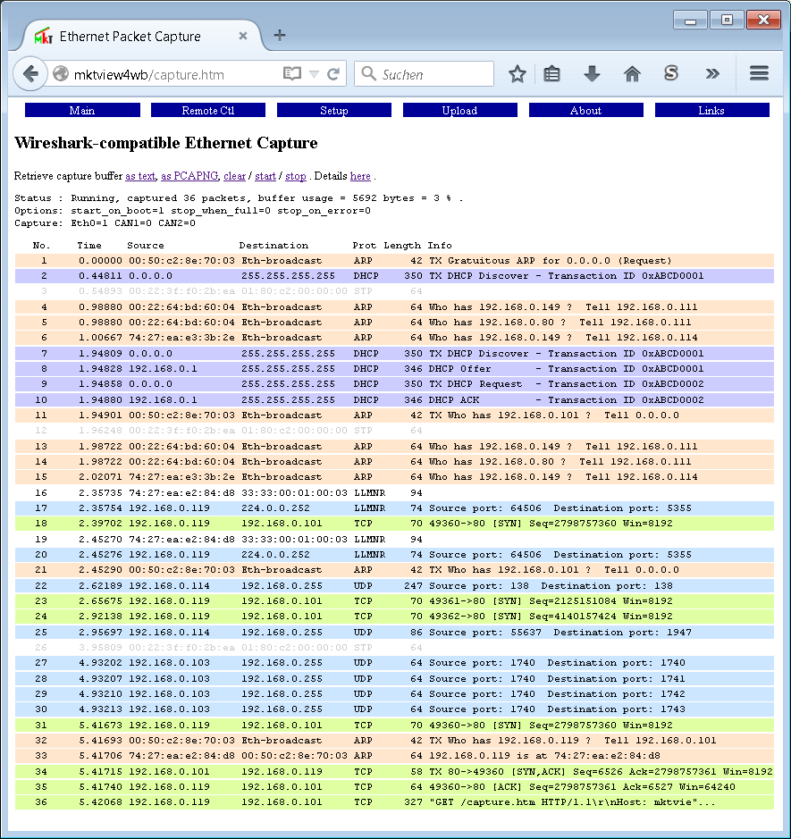
Browser-Screenshot with 'Ethernet Packet Capture'.
Click into the image to magnify it.
|
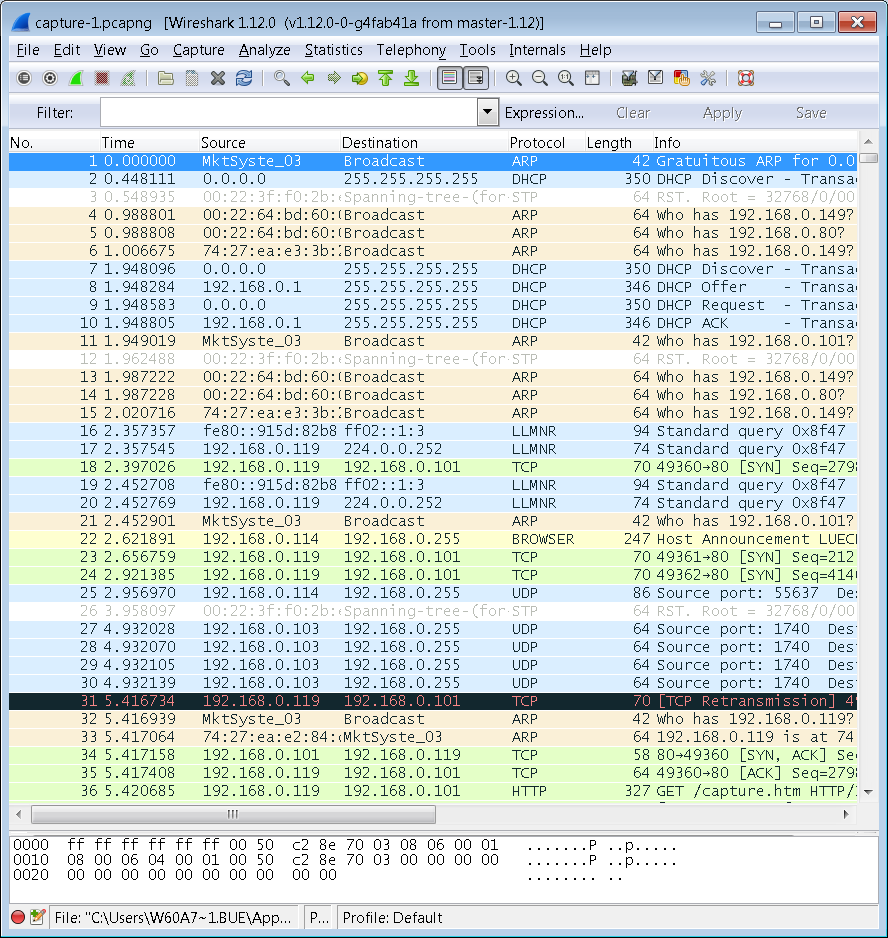
'Real' Wireshark screenshot showing the same captured data.
Click into the image to magnify it.
|
If you are concerned about privacy / network security:
The built-in packet capture is disabled by default - you need to activate it in the
system setup
("locally") before you can use it. The commands listed above (e.g. "/start" via browser) only work
if the system setup (stored in EEPROM) allows it. Furthermore you must be logged in
(on the 'Device Setup' page) to control the Packet Capture remotely,
and to read the buffer as a PCAPNG file via HTTP.
Without being logged in, it's impossible to start / stop / clear the capture, and to retrieve the capture as PCAPNG file.
Without being logged in, the packet capture buffer can only be displayed 'as text' (*.txt or *.htm) in the web browser.
The direct display as HTML lacks many of the features in Wireshark (recognized protocols, protocol errors,
interactive inspection / decoding of thousands of different 'fields' in the TCP/IP data, ..).
Thus, to analyse Ethernet and TCP/IP traffic, we recommend to open the captured data
in Wireshark (as shown in the right screenshot above).
User-friendly browsers can be configured to open Wireshark automatically when recognizing a PCAPNG file.
The browser then downloads the capture buffer (capture.pcapng) and stores it as a PCAPNG file, launches Wireshark,
which then loads and displays the captured frames in a matter of seconds.
Many protocol errors and -warnings can only be detected by Wireshark, like the
'TCP Retransmission' in Paket Nr. 31 in the screenshot (right side) shown above.
Similar applies to the multitude of protocols recognized and analysed by Wireshark. For example,
the tiny 'capture display' integrated in the MKT-device can only tell 'UDP' from 'TCP',
while Wireshark knows if a packet's protocol type is ARP, DHCP, LLMR, BROWSER, DHCPv6, NBNS, HIP, HTTP, etc etc...
When inspecting the capture buffer via web browser, the direction (RX/TX)
of CAN frames is indicated by the background colour:
Blue : Received frames (from the device's point of view),
Green: Transmitted frames (from the device's point of view).
Unlike the display in Wireshark, CAN message identifiers are not shown in the 'Info' field but in the column titled 'Source' (for received frames, blue)
or 'Destination' (for frames transmitted by the device, green).
11-bit message identifiers are displayed with 3 hex digits, 29-bit IDs with 8 digits.
For CAN, the 'Info' field only shows the data field (max. 8 bytes, hexadecimal without prefix). Example:
Packet Capture Status : Running, captured 5 packets .

    No.    Time    Source            Destination     Prot Length Info
| 1 0.00000 CAN1:0x07B CAN 8 00 02 03 04 05 06 07 08 |
| 2 0.13405 CAN1:0x000003FF CAN 8 05 44 4C 34 59 48 46 20 |
| 3 0.43712 CAN1:0x07B CAN 8 01 02 03 04 05 06 07 08 |
| 4 0.53385 CAN1:0x000003FF CAN 8 05 44 4C 34 59 48 46 20 |
| 5 3.12532 192.168.0.206 192.168.0.234 TCP 117 TX "HTTP/1.0 200 OK\r\nContent-Type:"... |
See also: Wireshark Tricks
in the UPT programming tool's online help system .
A suitable web browser (like Firefox, Chrome or Iron) can access various memory areas
in the device via HTTP (Hypertext Transfer Protocol).
In devices with an SD memory card, also 'real' files (on the FAT-formatted storage medium) can be accessed.
Since only the HTTP 'GET' protocol is supported (but not FTP = File Transfer Protocol), files
cannot easily be deleted or written so far.
Details about the pseudo-file-system are in the
online help system
of the programming tool (available online at the MKT website).
The (pseudo-) file system's "root" can be examined via web browser by entering
<IP-address>/files/ or (alternatively) <Hostname>/files/
in the browser's address bar.
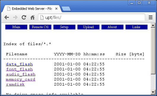
In devices with memory card adapter, entries in the root may link to real
(not just 'pseudo') file systems. For those entries, the directory listing will
contain 'clickable links' (in the HTML page) which allows reading those files..
Other entries (like data_flash, audio_flash, font_flash, etc) are no 'real' file-based
storage media; instead they represent different address ranges in the devices
Flash memory chip(s). Some of the 'files' in those chips may still be accessable
'like a disk file' even though their internal representation is different.
This part of the device's built-in Flash memory is used to store the application.
The elements in this area are not accessable 'as a file'.
This area can be used to store audio samples, which can be replayed (through the speaker)
by the application.
If an application uses user-defined fonts, they will automatically transferred
into this memory area by the programming tool. They may be accessable like files.
This folder may also contain an optional 'Boot-Screen'
(BOOTSCRN.BMP, with a company logo or similar displayed immediately after power-on).
This feature only exists in devices with a memory card adapter, for example MKT-View II / III / IV (SD memory).
Files on the memory card can be listed as a directory, and can be accessed (read, not write) via HTTP
(Hypertext Transfer Protocol) even if they are not Hypertext (*.htm) at all.
The RAMDISK is used as an intermediate storage (buffer) when uploading files
via web browser (from the PC into the programmable device). Details about that is in the next chapter.
In addition, the Script Language
can write (create) own files in the RAMDISK, which can be be read via web browser.
Certain files can be uploaded from the PC (web browser) into the embedded device via HTTP.
If the device still uses the default name ("UPT"), the 'Upload' page is at upt/upload.htm.
Click the button labelled "Browse" (or "Durchsuchen" on a german PC; the browser decides which name to use).
Depending on the operating system, this opens a file selector box. Select the file you want to upload there.
The complete path and name of the selected file will be displayed in the text input field next to that button.
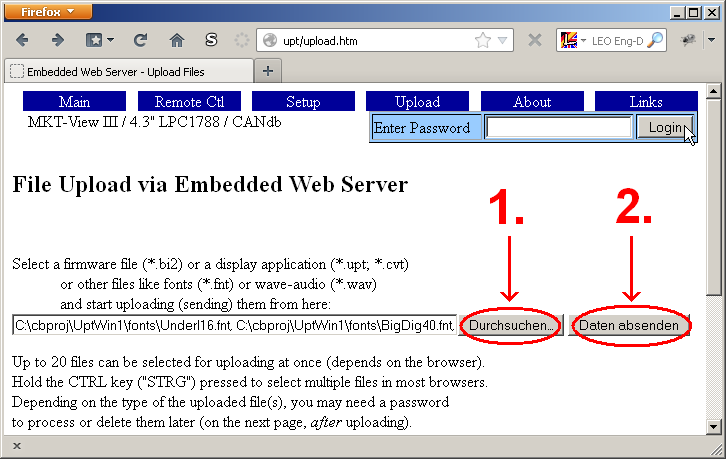
Screenshot of the 'Upload Files' page on a german PC.
If you are really sure you want to upload the selected file, click the second button.
Depending on your browser, operating system, and language, this button is labelled "Send", "Daten absenden", or something like that.
Uploading may take a few seconds, so please be patient until the browser switches to a new page.
After uploading one or more files into the RAMDISK, the target device will check the file types and integrity.
If the file is one of the 'special types', the firmware will take appropriate action when clicking
the 'Process' button (you must be logged in with a password for this step).
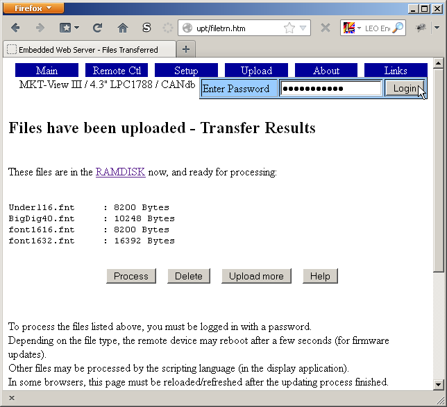
Screenshot of the 'Files Transferred' page on a german PC.
After clicking the 'Process' button (see screenshot above), it may take a few seconds until the display firmware
returns a status report (about the prossed files) as in the screenshot below. Uploaded files will be treated as follows:
- *.upt; *.cvt : Display applications will be parsed (converted to binary data) and copied to FLASH memory.
When successfull, the *.upt (or *.cvt) - file will automatically be deleted from the RAMDISK.
- *.bi2 : Firmware updates will remain in the RAMDISK until the system reboots in "bootloader-mode".
When 'processing' such a file, the bootloader will prompt the operator to confirm the firmware update.
Note: Last not least for security reasons, it's impossible to confirm a firmware update remotely,
at least not for devices with an own keypad, touchscreen, or similar.
New firmware info:
 Art-Nr. : 11532 (depends on the device)
 Version : X.Y.Z
 Compiled: Month, Day, Year of compilation.
 FW: MKT-View IV / 7" LPC4357 / CANdb
    -----------------------------------
   | Is this the firmware you wanted ? |
   |    Press ENTER/OK/F1 to CONFIRM,  |
   |    or any other key to abort.     |
----------------------------------- |
After 'flashing' the new firmware (copying from RAMDISK into the firmware Flash memory),
press the ENTER key (or whatever replaces it) again, to reboot with the new firmware.
See also: Firmware Update via Memory Card.
- *.fnt : user defined fonts will be transferred into the 'font-flash', if supported by the target device.
When successfully copied to FLASH, these files will be deleted from the RAMDISK automatically.
- *.wav : wave audio files will be transferred into the 'audio-flash', if the device supports such a storage medium.
When successfully copied to FLASH, these files will also be deleted from the RAMDISK automatically.
- Files with other 'special' extensions may be processed in some other ways, which was unknown at the time of this writing.
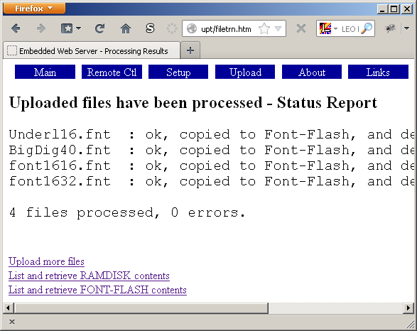
Screenshot of the 'Status Report' after processing uploaded files.
Without processing, the uploaded files will simply remain in the RAMDISK, unless a
script
in your application takes care of them and processes it in some way (read it, display it, play it as an audio file, delete it, ...).
To upload files without processing as shown above, you do not need to log in with a password. But again, files uploaded
that way will simply remain in the RAMDISK, where they cannot do any harm (besides occupying space in the restricted RAMDISK).
Uploaded files can also be accessed later (again, via embedded web server).
To retrieve the RAMDISK directory, and find out how many kilobytes of disk space are available to upload files,
try upt/files/ramdisk (remember to replace "upt" in the address by your device's own name,
if you have modified it).
- Note
- A kilobyte is 1024 bytes. It always was, since the early days of computing.
There is no changing this. None of this "kibibyte" crap.
Don't let certain harddisk manufacturers convince you 1000 bytes are a 'kilobyte' now !
Certain pages have "dynamic content", which is realized by special tokens
(not HTML-tags!) in the original HTML code. These tokens are recognized by
the HTTP server, and replaced with the actual values.
The following tokens have been implemented so far
(without space between the '$' and the tree-letter-token):
-
"$ AIV $" = analog input measuring the 'supply' voltage
(3 digits, 0.0 ... 36.9 Volt)
-
"$ AIv $" = analog input measuring the 'supply' voltage
(3 digits, PERCENT, 000%=0V, 100%=24 V)
-
"$ AIU $" = analog input measuring the 'Ultracap' voltage (for devices with internal uninterruptable power supply)
(3 digits, 0.00 ... 5.19 Volt)
-
"$ AIT $" = analog input measuring the temperature
(3 digits, 0.0 ... 49.9 °C)
-
"$ AIt $" = analog input measuring the temperature
(3 digits, 0 = 0°C ... 100 = 100°C )
-
"$ FWA $" = Firmware Article (5-digit number)
"$ FWN $" = Firmware Name (descriptive string like 'MKT-View II 480*272
TFT')
"$ FWV $" = Firmware Version (or compilation date)
-
"$ RTC $" = reads the Real Time Clock, ISO-formatted date and time (YYYY-MM-DD
hh:mm:ss).
May return 'RTC not available' if no RTC is installed, or not supported by
the firmware / driver.
If the displayed value is wrong, enter the system menu (possible via TELNET)
and adjust it.
-
"$ SCH $" = Screen-Height in pixels ( 3 or 4 digits).
"$ SCW $" = Screen-Width in pixels ( 3 or 4 digits).
Used, for example, in the framebuffer image so the browser knows the size
of the image before loading it .
-
"$ SNR $" = The device's Serial Number (usually 4 or 5 digits).
-
"$ SIP $" = Server IP. This is the HTTP Server's own, local, IP address.
The result is something like 192.168.0.242 (as configured in the terminal's
NETWORK SETUP menu). Because the HTTP server doesn't know the IP on the 'other
side' of a DSL router or similar, the IP returned by $SIP only works within
the local network (LAN), not through the "internet" (world wide web).
Anyway, the simple HTTP server was not designed to be a WWW-server, and
completely lacks the security mechanisms found in fully-fledged servers like
Apache !
The purpose of this function was to build a link to the built-in TELNET server,
which can be invoked through a link like "telnet://192.168.0.242" .
Using the $SIP function, the above link is coded as
<A HREF="telnet://$SIP$">telnet://$SIP$</A>
Most of the tokens listed above are used in the server's 'index' page, so
the same index page (sourcecode) can be used in a lot different firmware
variants.
Besides the special tokens listed above, the HTTP server also recognizes
certain file names. At the moment, these are:
-.. . -.. .-.. ....- -.-- .... ..-. ...-.-
At the moment, this chapter only contains a few notes from the developer,
who had no experience with "Vista" and "Windows 7" (in favour of XP).
The next paragraph shows how to configure a PC running Windows 7 for a point-to-point connection via Ethernet (cable)
to a programmable device with fixed IP address (i.e. without DHCP).
Since the author's PC only had a german user interface for Windows 7 installed, the following paragraph
is in german language.
-...-
Das folgende Kapitel enthält eine kurze Beschreibung, wie eine Punkt-zu-Punkt-Verbindung per Ethernet-Kabel
zwischen einem PC mit Windows 7 und einem programmierbaren Gerät mit fester IP-Adresse (hier: MKT-View III)
hergestellt werden konnte.
Da auf dem privaten Notebook des Autors nur Windows 7 in deutscher Sprache installiert war, ist die folgende
'Kurzanleitung' auch nur in deutscher Sprache verfügbar.
- "Start" in der linken unteren Ecke, "Systemsteuerung".
- "Netzwerk und Freigabecenter"
- "Adaptereinstellungen ändern"
(im Fenster mit dem Titel "Systemsteuerung - Netzwerk und Internet - Netzwerkverbindungen")
- auf das Symbol für die "LAN-Verbindung" (d.h. Ethernet-Schnittstelle) klicken,
über die später die Verbindung zum programmierbaren Gerät aufgebaut werden soll.
(Siehe Screenshot 'Auswahl der LAN-Verbindung' am Ende dieses Kapitels)
- Unter dem Symbol darf, wenn die Kabelverbindung zum Gerät hergestellt ist, KEIN ROTES KREUZ erscheinen !
(das rote Kreuz soll wohl andeuten, dass die Verbindung "physikalisch" nicht funktioniert)
- Doppelklick auf das Symbol "LAN-Verbindung". Es sollte sich ein Fenster mit dem Titel "Status von LAN-Verbindung" öffnen.
(Siehe Screenshot 'Status von LAN-Verbindung' am Ende dieses Kapitels)
- In besagtem Fenster den Button namens "Eigenschaften" anklicken
- In der Liste unter "Netzwerk" den Eintrag "Internetprotokoll Version 4 (TCP/IP)" markieren.
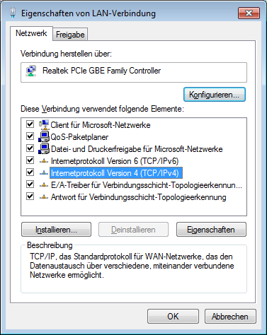
- Klick auf "Eigenschaften" (unter der Liste mit den Netzwerkprotokollen).
Es öffnet sich ein weiteres Fenster:
(Details zur IP-Adresse, Subnetzmaske, und dem Standardgateway folgen später)
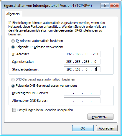
- Da bei einer Punkt-zu-Punkt-Verbindung zwischen Windows (7) und dem programmierbaren Gerät
kein DHCP-Server zur Verfügung steht, muss wohl oder übel die Option
(o) Folgende IP-Adresse verwenden:
aktiviert werden, und im darunterliegenden Feld eine noch freie IP-Adresse
eingegeben werden (ähnlich wie im obigen Screenshot).
Im oben gezeigten Screenshot wurde im programmierbaren Gerät die feste IP-Adresse 192.168.0.206
verwendet. Wichtig:
Da in der beschriebenen Konfiguration (Notebook direkt über Ethernet-Kabel mit dem Gerät verbunden) kein DHCP-Server
zur Verfügung stand, darf auch im programmierbaren Gerät kein DHCP verwendet werden !
Die ersten drei Bytes in den IP-Adressen (hier: 192.168.0) müssen bei allen Geräten im Netzwerk identisch sein.
Üblicherweise ist die Subnetzmaske für diese drei Bytes immer '255.255.255'; das letzte Byte der Subnetzmaske ist
üblicherweise Null. Eine detailierte Erklärung würde den Rahmen dieses Dokuments sprengen; fragen Sie ggf. Ihren
Netzwerk-Spezialisten !
Zu den obigen Screenshots passende Einstellungen im 'Network Setup' des programmierbaren Gerätes:
       NETWORK SETUP

       MAC: 00-50-C2-8E-70-00
       Name: UPT2
       DHCP: disabled (static IP)
        IPaddr: 192.168.000.206
        Subnet: 255.255.255.000
        Gatew.: 192.168.000.001
       Local TCP Server Ports:
        HTTP:80 TN:23 FTP:21
       CAN via UDP: off
        RemoteIP: 192.168.000.242
        Ports: R=55556 L=55557
Zusammenfassung der Screenshots von den Netzwerk-Einstellungen unter Windows 7 (64-Bit, auf dem Notebook des Autors):
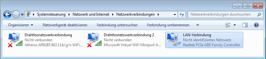
(Auswahl der LAN-Verbindung, aka 'Ethernet-Port', unter Windows 7)
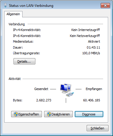
("Status von LAN-Verbindung", nach Doppelklick auf den Adapter aus dem vorherigen Screenshot)
("Eigenschaften von LAN-Verbindung", nach Klick auf "Eigenschaften" unter 'Status von LAN-Verbindung' [s.O.] )
("Eigenschaften von Internet Protokoll Version 4 (TCP/IPv4)",
nach Klick auf "Eigenschaften" unter 'Eigenschaften von LAN-Verbindung' [s.O.],
wenn dort der Eintrag 'Internetprotokoll Version 4 (TCP/IPv4)' markiert ist )
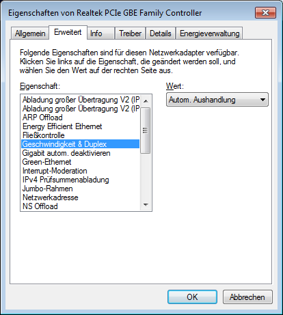
("Eigenschaften des Ethernet-Controllers im PC", hier: Realtek PCIe im Notebook des Autors)
Mit den oben gezeigten Einstellungen funktionierte -zumindest auf dem Notebook des Autors, einem HP630-
die Verbindung zum Web-Server des programmierbaren Gerätes unter Windows 7, 64 Bit, "Home Premium", problemlos.
Das programmierbare Gerät (MKT-View III) konnte per Browser (Firefox) sowohl über die IP-Adresse (192.168.0.206)
als auch über den Hostnamen (hier: UPT2) des Gerätes angesprochen werden.
Hinweise zur IP-Konfiguration:
- IP-Adresse :
- Fragen Sie ggf. Ihren Netzwerk-Administrator, ob eine feste IP-Adresse im Netzwerk zulässig ist,
und tragen Sie diese IP-Adresse im entsprechenden Eingabefeld ein.
Eine IP-Adresse darf im gesamten (lokalen) Netzwerk nur ein einziges Mal vorkommen,
d.h. die IP-Adresse des PCs kann niemals mit der IP-Adresse des programmierbaren Gerätes identisch sein !
Falls DHCP verwendet wird (d.h. keine festen, sondern dynamisch zugewiesene IP-Adressen),
ist die Eingabe in diesem Feld belanglos, und das Gerät sollte statt über seine IP-Adresse über seinen Host-Namen
angesprochen werden.
- Subnetzmaske :
- Hier wird fast immer der Wert 255.255.255.0 eingestellt.
Falls DHCP verwendet wird (d.h. keine festen, sondern dynamisch zugewiesene IP-Adressen),
ist die Eingabe in diesem Feld belanglos.
- Standardgateway :
- Wird nur benötigt, wenn das Gerät eine Verbindung außerhalb des lokalen Netzwerks aufbauen muss;
z.B. wenn das Gerät (oder der PC) aus irgendwelchen Gründen eine Verbindung mit dem Internet aufbauen muss.
Falls DHCP verwendet wird (d.h. keine festen, sondern dynamisch zugewiesene IP-Adressen),
ist die Eingabe in diesem Feld belanglos.
http://UPT ( = default hostname
of most programmable devices, including MKT-View. Requires Ethernet
LAN )
Network Setup in the display terminal, part of document #85115, "System Setup"
A list of other 'printable manuals' from the MKT Website / "MKT-CD"
Website of MKT Systemtechnik